Devices for separation of biological materials
a biological material and device technology, applied in the direction of fluid pressure measurement, liquid/fluent solid measurement, peptide measurement, etc., can solve the problems of large sample volume and bulky current techniques
- Summary
- Abstract
- Description
- Claims
- Application Information
AI Technical Summary
Benefits of technology
Problems solved by technology
Method used
Image
Examples
example 1
[0200]A two-chamber fluidics cartridge containing a hydrogel coated microlectrode array was loaded into an ATS system. The microelectrode array comprised electrodes in a hollow ring shape, as depicted in FIG. 5. In one chamber, a standard solution with conductivity of 0.8 S / m and spiked DNA (genomic purchased from Promega or Lambda purchased from BioLabs) at 25 pg / μL was loaded for a total volume of 530 μL. In the other chamber, an unknown sample in a bodily fluid (blood, serum, plasma, sputum, etc. . . . ) was loaded to a total of 530 μL. The DNA was stained at a ratio of 1:5000× using YOYO®-1 green fluorescent dye purchased from Life Technologies. Both liquids were run on the ATS system at 10 Volts peak-to-peak and 15 kHz for 10 minutes while flowing at a variable flow rate (5 to 250 μL / min) (FIGS. 6 and 7). The arrays were then washed with an isotonic buffer (water+osmolites) for another 10 minutes at a variable flow rate in order to remove all matter that was not captured on the...
example 2
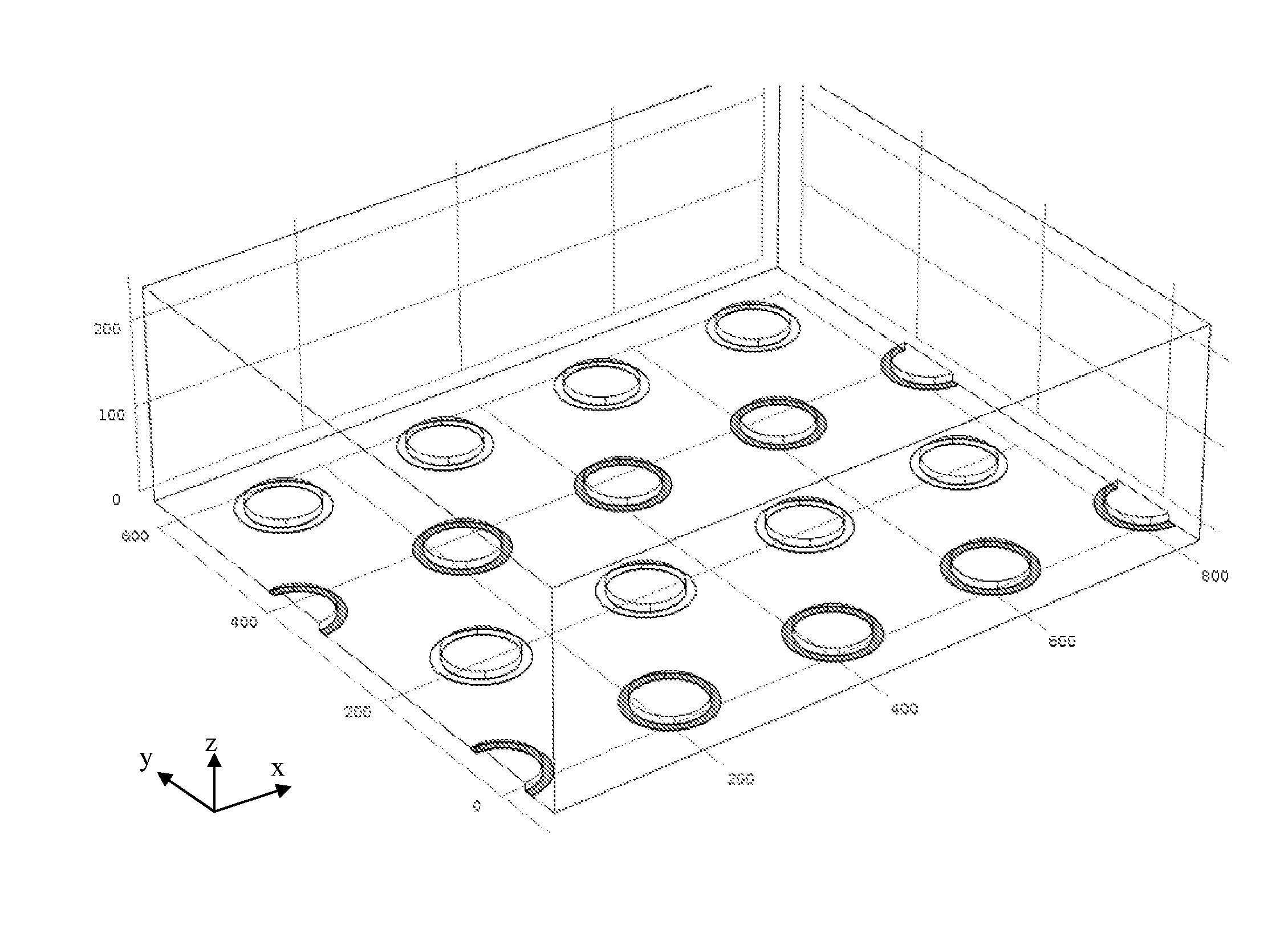
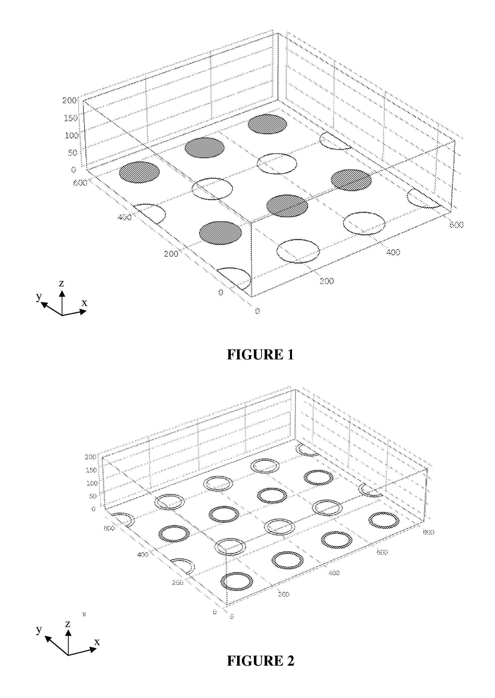
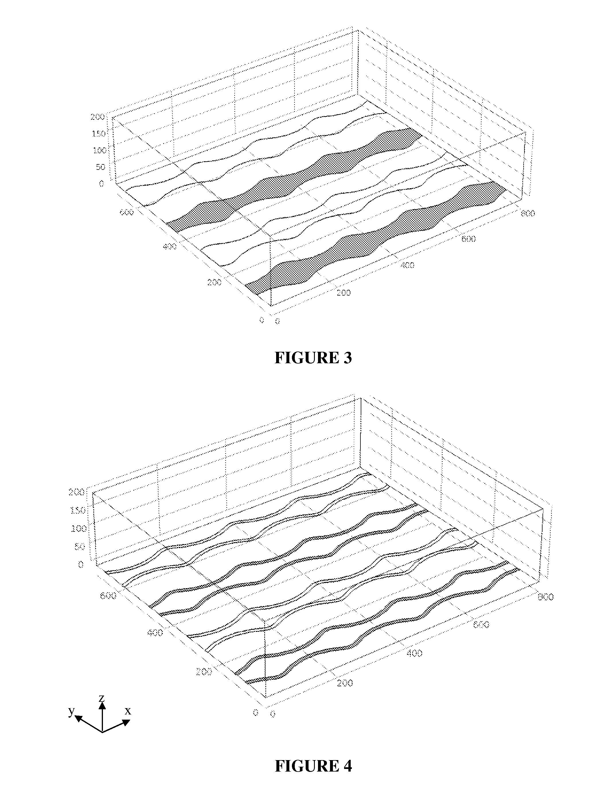
[0201]Various electrode designs were tested according to the methods described in Example 1. Generally, electrode geometry that increased FDEP while attenuating FFLOW enabled the stronger capture of nanoscale analytes. Below is a description of ACE performance difference between electrode designs.
TABLE 2Description of ACE performance differences between electrode designs.Electrode DesignRemarksHollow DiskStandard electrode geometry as shown in Figures 1, 6, 7, 8Hollow RingIncreased surface area for nanoscale analyte capture.Modification of flow pattern. Shown in Figure 2.Wavy LineProvides larger surface area for nanoscale analyte capture. Generates uni-axial flow.Shown in Figures 3 & 4.Hollow ring withReduces the ACET and ACEO. Shown in Figure 5.extruded centerBlocked ElectrodeReduces the ACET and ACEO. Not shown.Floating ElectrodeReduces ACET and ACEO, collectively FFLOW, while increasing FDEP. Shown in Figure 12.
PUM
| Property | Measurement | Unit |
|---|---|---|
| angles | aaaaa | aaaaa |
| angles | aaaaa | aaaaa |
| diameter | aaaaa | aaaaa |
Abstract
Description
Claims
Application Information
 - R&D
- Intellectual Property
- Life Sciences
- Materials
- Tech Scout
- Unparalleled Data Quality
- Higher Quality Content
- 60% Fewer Hallucinations
Browse by: Latest US Patents, China's latest patents, Technical Efficacy Thesaurus, Application Domain, Technology Topic, Popular Technical Reports.
© 2025 PatSnap. All rights reserved.Legal|Privacy policy|Modern Slavery Act Transparency Statement|Sitemap|About US| Contact US: help@patsnap.com


