CRC-based forward error correction circuitry and method

a circuitry and error correction technology, applied in the field of forward error correction (fec) circuitry and techniques, can solve problems such as delay in communication, consuming additional power in both transmitter and receiver, and information in the receiver digital baseband circuit b>12/b>-b>3/b> may be erroneous, etc., to achieve the effect of increasing delay

Active Publication Date: 2015-10-01
TEXAS INSTR INC
View PDF5 Cites 19 Cited by
  • Summary
  • Abstract
  • Description
  • Claims
  • Application Information

AI Technical Summary

Benefits of technology

The invention provides a way to add error correction capability to a communication system without needing an extra FEC encoder to insert extra bits. This can be done without increasing the bandwidth of the system, delaying message retransmissions, or changing the transmitted signal. The technical effect is improved error correction without adding extra complexity to the system.

Problems solved by technology

The foregoing circuitry and the transmission media may introduce errors into the digital information, so the information in the receiver digital baseband circuit 12-3 may be erroneous.
Unfortunately, such retransmissions add delay to the communication, consume additional power in both the transmitter and receiver, and waste channel bandwidth.
Furthermore, there typically is a limit to the number of the retransmissions that are allowed.
When that limit is reached, the connection established between the transmitter and receiver may be terminated, in which case that connection would need to be restarted, thereby incurring further communication overhead between the transmitter and receiver.
Unfortunately, the quality metric is generally not a good indicator of error locations in modern digital receivers that typically utilize available maximum likelihood estimation types of algorithms in the demodulation process.
As a result, error correction performance in the system shown in above described Prior Art FIG. 1B and described in U.S. Pat. No. 7,577,899 is quite limited.
This is inefficient from the viewpoints of power consumption and bandwidth.
Note that retransmission is costly in terms of power in both transmitter and receiver and in terms of increased delay.
There also is an unmet need for a way to provide error correction capability in a communication system including a transmitter and a receiver that may include error detection capability but does not have CRC-based FEC error correction capability, without increasing latency due to message retransmissions necessitated by detected but uncorrected bit errors.

Method used


Image

  • CRC-based forward error correction circuitry and method
  • CRC-based forward error correction circuitry and method
  • CRC-based forward error correction circuitry and method

Examples


Embodiment Construction

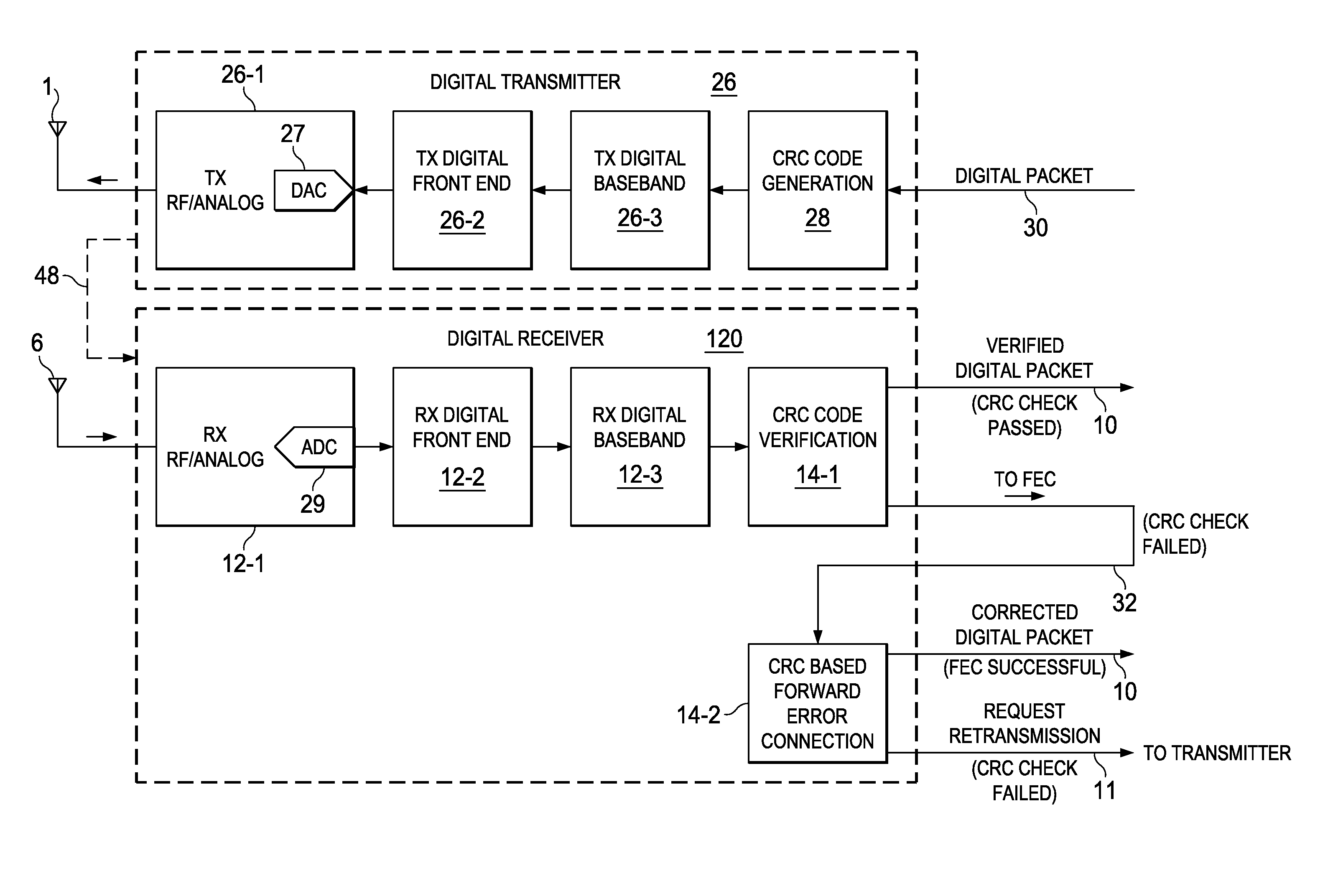
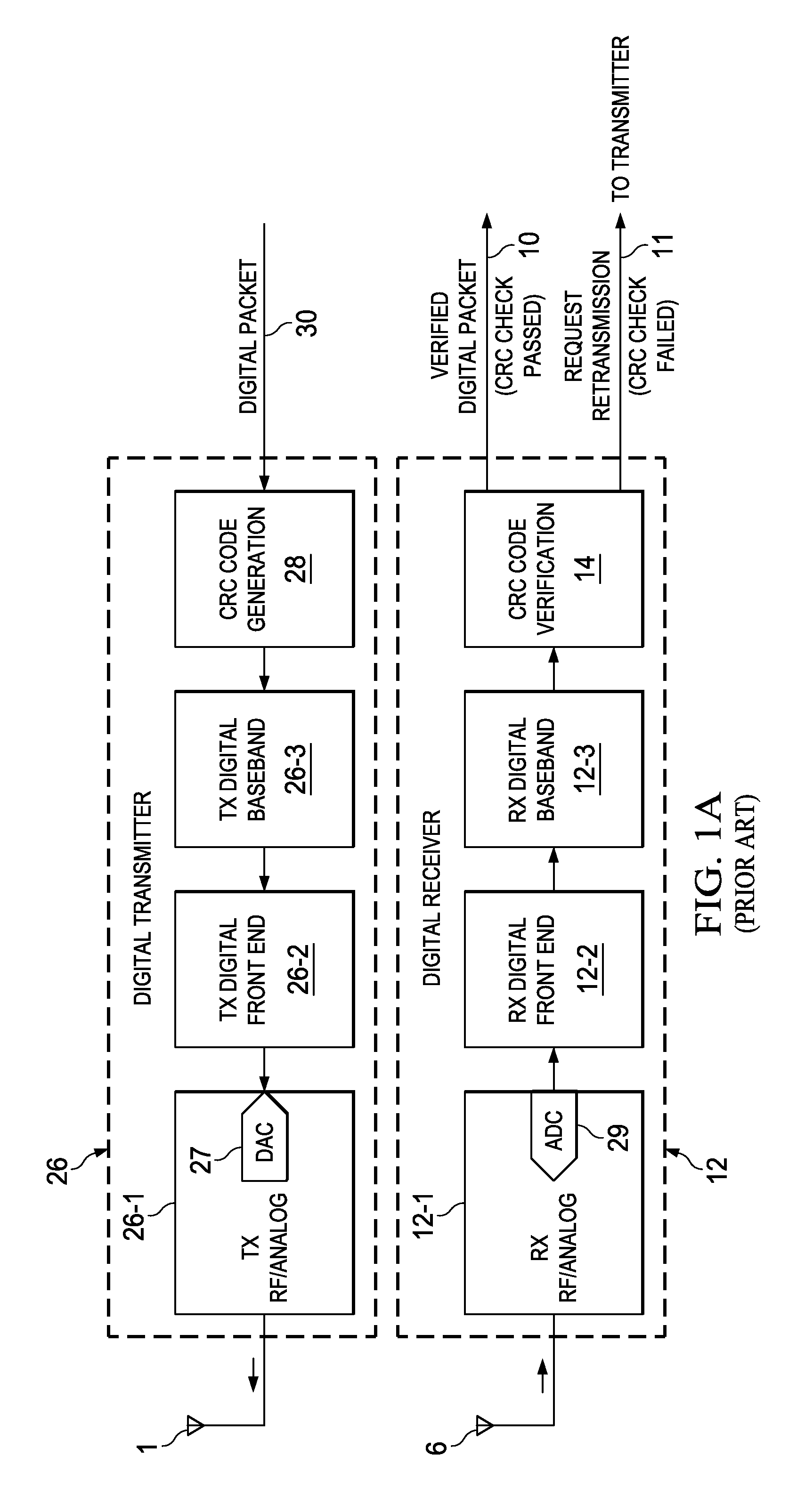
[0055]FIG. 2 shows a communication system including CRC error correction capability that may be incorporated into any conventional communication system which includes a transmitter and a receiver that includes CRC error detection capability but does not include CRC error correction capability. For example, the wireless communication system of FIG. 2 may be incorporated into a conventional BLE system which has no CRC error correction capability, generally as shown in Prior Art FIG. 1A. However, the communication system does not have to be wireless, and the transmitter actually can be coupled to the receiver by means of a cable, for example as indicated by the dashed line 48 extending from an output of a digital transmitter 26 to an input of a digital receiver 120. For example, USB power delivery systems transmit data packets over a cable but can still benefit from CRC-based forward error correction in accordance with the invention described herein. (However, if the transmitter is cou...


PUM


Abstract

A communication system includes digital transmitter circuitry (26) including a CRC (cyclic redundancy check) generator circuit (28) generating a first CRC code based on a message and appending the CRC code to the message a first data packet, and circuitry (26-1,2,3) transforming the first data packet to provide a second data packet and transmitting it. Digital receiver circuitry (120) includes circuitry (12-1,2,3) receiving the second data packet, a CRC verification circuit (14-1) comparing a received digital CRC code portion of the second data packet to a calculated digital CRC code portion including any introduced error to detect the existence of any error in the second data packet. The message is presented for further processing if no error is detected, and a CRC-based FEC (forward error correction) circuit (14-2) receives the message and calculated digital CRC code from the verification circuit if an error is detected, corrects the detected error, and indicates the error is uncorrectable if the correction is unsuccessful.

Description

BACKGROUND OF THE INVENTION[0001]The present invention relates generally to forward error correction (FEC) circuitry and techniques which may be added to an existing digital communication system including a transmitter and a receiver including any CRC (cyclic redundancy check) for error detection.[0002]Conventional forward error correction includes use of a FEC encoder (such as BCH or LDPC in the transmitter to add parity bits. The parity bits are sent via suitable media, which may be a noisy data signal channel, along with a data packet. The corresponding receiver uses a matched FEC decoder and parity bits to correct errors introduced during transmission and to recover the data. (BCH codes form a class of cyclic error-correcting codes that are constructed using finite fields. Binary BCH codes that may be used to correct multiple bit errors. Another advantage of BCH codes is the ease with which they can be decoded by an algebraic syndrome decoding process which simplifies the decode...

Claims


Application Information

Patent Timeline
Patent Type & Authority Applications(United States)
IPC IPC(8): G06F11/10H03M13/09H04L1/00
CPCG06F11/1004H03M13/09H04L1/0045H04L1/0041H04L1/0061H04L1/16
Inventor REN, JING-FEIGOEL, MANISHZHU, YUMING
Owner TEXAS INSTR INC
Why Eureka
Try Eureka