Cmu cooling tower and method of construction

a technology of water cooling towers and water towers, applied in the direction of heating types, building repairs, separation processes, etc., can solve the problems of under-performing cooling towers, affecting the efficiency and therefore the operating costs of hvac and industrial systems, and replacing or supplemental cooling towers, so as to reduce the time of construction and operation, less heavy equipment, and less transportation

Inactive Publication Date: 2015-10-01
SYNTECH TOWERS L L C
View PDF6 Cites 8 Cited by
  • Summary
  • Abstract
  • Description
  • Claims
  • Application Information

AI Technical Summary

Benefits of technology

[0015]The present invention provides a cooling tower constructed of multiples of standard concrete masonry units (CMUs) properly reinforced, using standard CMU construction methods and specifications, and using masons of ordinary skill, costing less for construction and maintenance, requiring less heavy equipment, less transportation and lifting of heavy and large components, a smaller construction work site, and requiring significantly less time to construct and make operational.

Problems solved by technology

Many existing buildings also need replacement or supplemental cooling towers because of the inadequacy of present cooling towers due to increased demands, higher temperatures, consolidation into campus-wide HVAC systems, or deteriorating performance of existing cooling towers.
An under-performing cooling tower can be a large problem for commercial properties, medical facilities, and industries, affecting the efficiency and therefore the operating costs of HVAC and industrial systems, and affecting the comfort and therefore the satisfaction, health, and productivity of persons.
But replacement requires taking an existing cooling tower out of service and waiting for the construction of a new cooling tower to be completed.
Cooling towers must be located outside, take up a lot of space, can be noisy, and might generate some mist or vapor.
Such locations present problems in the construction and installation of cooling towers.
Industrial cooling towers made of wood in the traditional way are susceptible to fire and to rot and early deterioration in the constantly wet cooling-tower environment, requiring proper preparation and constant maintenance throughout the operational life of the cooling tower.
Cooling towers made of steel are known, but are very expensive, very heavy to transport and erect, and require highly skilled workers in the design phase, any pre-fabrication phase, and in the erecting or construction phase, in order to avoid potential failure, improper fitting of components, or even injury to persons and property.
Also, steel is subject to rusting and deteriorating in the constantly wet environment if it is not properly prepared and constantly maintained throughout the operational life of the cooling tower.
The construction of such a tower is a major undertaking requiring many months, even a year, to complete.
The logistics and heavy equipment required are extensive.
Such traditional towers have underground basins and require extensive engineering and design in advance of construction.
All of the presently known methods of constructing cooling towers have at least one of the disadvantages of being insufficiently durable, too expensive, too difficult to transport, too long to place into operation, too difficult to erect or construct without highly skilled labor and long-term use of heavy machinery, and too difficult to maintain over the operational lifetime of the cooling tower.

Method used


Image

  • Cmu cooling tower and method of construction
  • Cmu cooling tower and method of construction
  • Cmu cooling tower and method of construction

Examples


Embodiment Construction

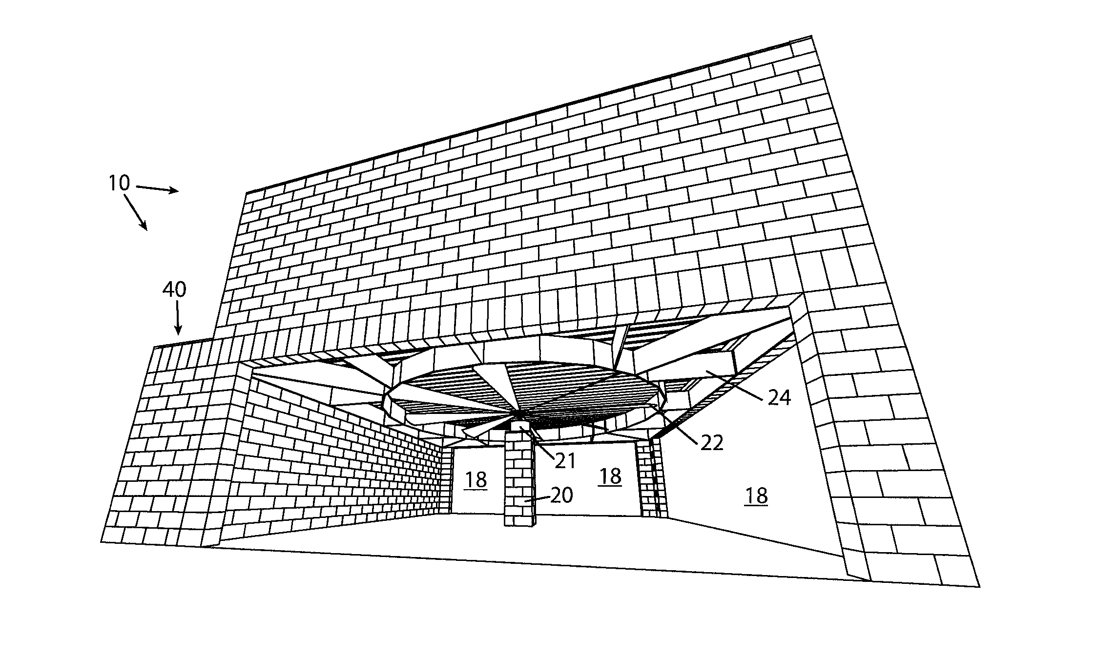
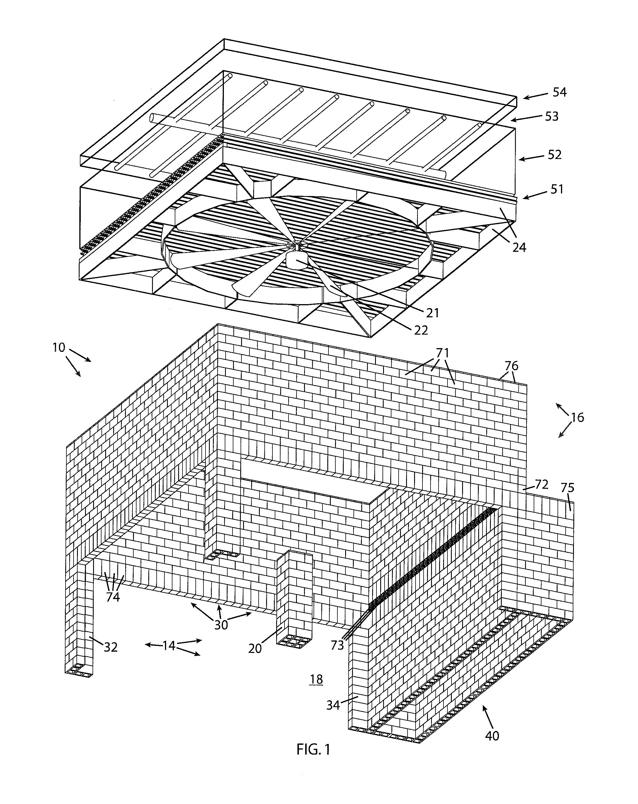
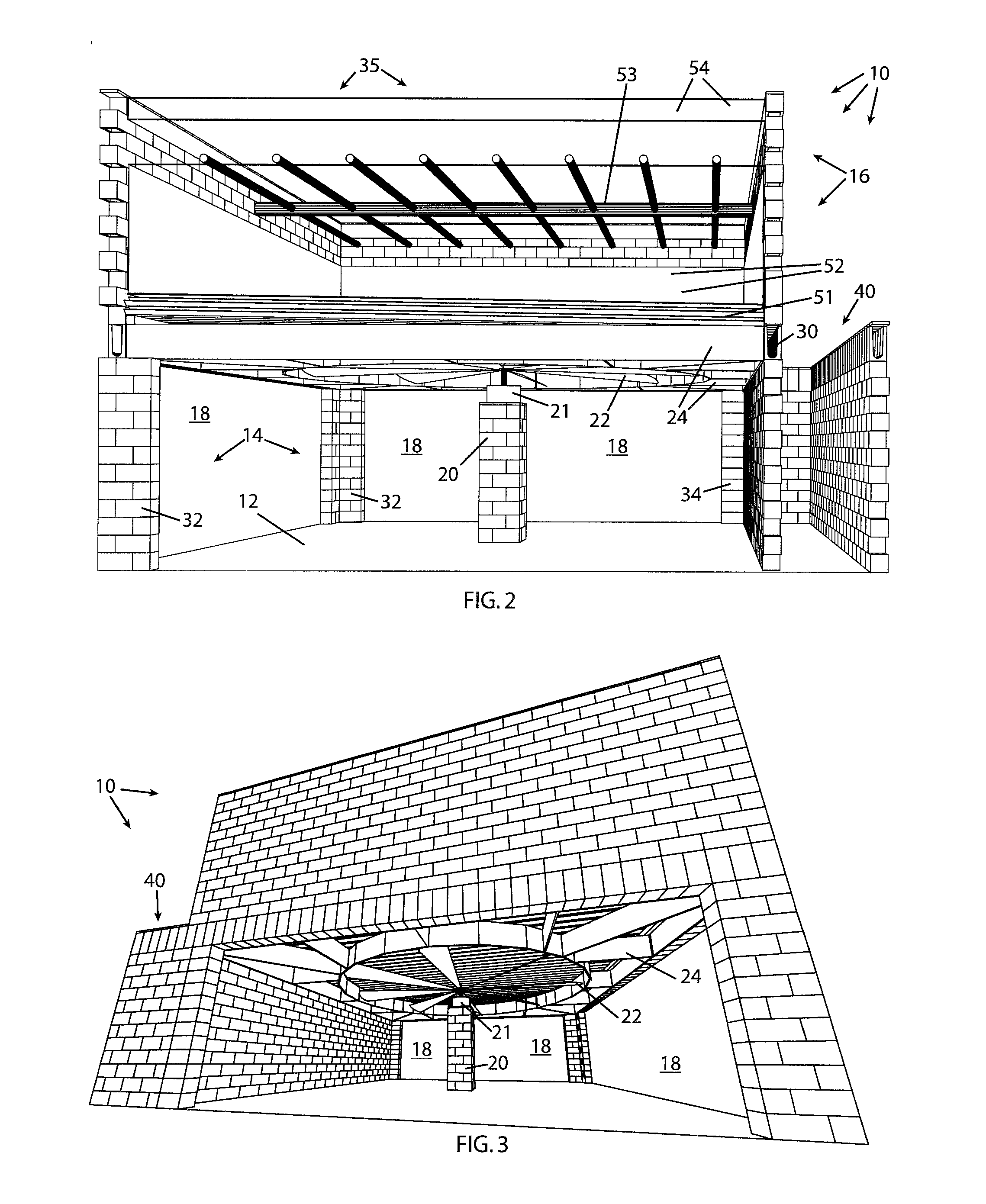
[0033]Referring to FIG. 1&FIG. 2 the counterflow type of cooling system known in the art comprises, from top to bottom, an optional drift eliminator 54 for the purpose of catching sprays and mists of water and retaining them in the cooling system, a nozzle array 53 that sprays water to maximize the available surface area of water droplets for evaporative cooling, a thick layer of porous fill media 52 to further spread out the water droplets and to prolong their exposure to the cooling stream of air, and a water collector 51 that catches and channels the cooled water but allows the flow of cooling air from below.

[0034]The forced-air counterflow type of cooling system known in the art further comprises a fan 22 driven by a fan motor 21 and surrounded by a fan shroud 24, with the fan assembly located below the rest of the cooling system, which puts the fan assembly closer to the ground or mounting surface, which is advantageous for maintenance purposes and for weight-distribution purpo...


PUM

PropertyMeasurementUnit
sizeaaaaaaaaaa
sizeaaaaaaaaaa
sizeaaaaaaaaaa

Abstract

A cooling tower structure and method of construction using multiples of standard concrete masonry units (CMUs) properly reinforced, using standard CMU construction methods and specifications, and using block masons of ordinary skill, costing less for construction and maintenance, requiring less heavy equipment, less transportation and lifting of heavy and large components, a smaller construction work site, and requiring significantly less time to construct and make operational.

Description

BACKGROUND OF THE INVENTION[0001]This invention provides a method of constructing water cooling towers using concrete masonry units (CMUs) more quickly, at lower cost, requiring no heavy construction equipment, resulting in a more durable, fire-resistant, longer lasting and easier to maintain structure than is presently known.[0002]Water cooling towers are well known, and are a common heat-exchange component in large commercial, medical, and industrial HVAC systems, in cooling for industrial processes, and aeration of water for other purposes. Cooling towers are a standard part of new construction of buildings or campuses of buildings. Many existing buildings also need replacement or supplemental cooling towers because of the inadequacy of present cooling towers due to increased demands, higher temperatures, consolidation into campus-wide HVAC systems, or deteriorating performance of existing cooling towers.[0003]An under-performing cooling tower can be a large problem for commercia...

Claims


Application Information

Patent Timeline
Patent Type & Authority Applications(United States)
IPC IPC(8): F28C1/00E04C1/00E04H5/12E04B1/04
CPCF28C1/00E04B1/04E04B2103/02E04H5/12E04C1/00E04B9/02E04C2003/023F28C1/16Y02B30/70
Inventor MARKS, RONALD J.SPRING, MARK B.SPRING, DAVIN O.
Owner SYNTECH TOWERS L L C
Why Eureka
Try Eureka