
Projected scale for depth measurement

a projected scale and depth measurement technology, applied in the field of projected scale for depth measurement, can solve the problems of inability to accurately determine the penetration depth of the device, the device described above for determining the penetration depth according to the prior art has a relatively complex construction and handling, and the incorrect use of the device can occur frequently

Inactive Publication Date: 2018-11-20
HILTI AG
View PDF12 Cites 0 Cited by
  • Summary
  • Abstract
  • Description
  • Claims
  • Application Information

AI Technical Summary

Benefits of technology

The present invention provides a device for determining the depth of penetration in a hole that is drilled into a workpiece using a drilling machine. This device is designed to be simpler and cheaper to use than previous devices.

Problems solved by technology

Furthermore, devices for determining a penetration depth can also have a more complex configuration, as is explained below.
The devices described above for determining a penetration depth according to the prior art have relatively complex construction and handling.
Because of this complexity, incorrect use of these devices can frequently occur.
Furthermore, due to their complexity these devices are susceptible to malfunction, difficult to maintain and expensive.

Method used


Image

  • Projected scale for depth measurement
  • Projected scale for depth measurement
  • Projected scale for depth measurement

Examples


second embodiment

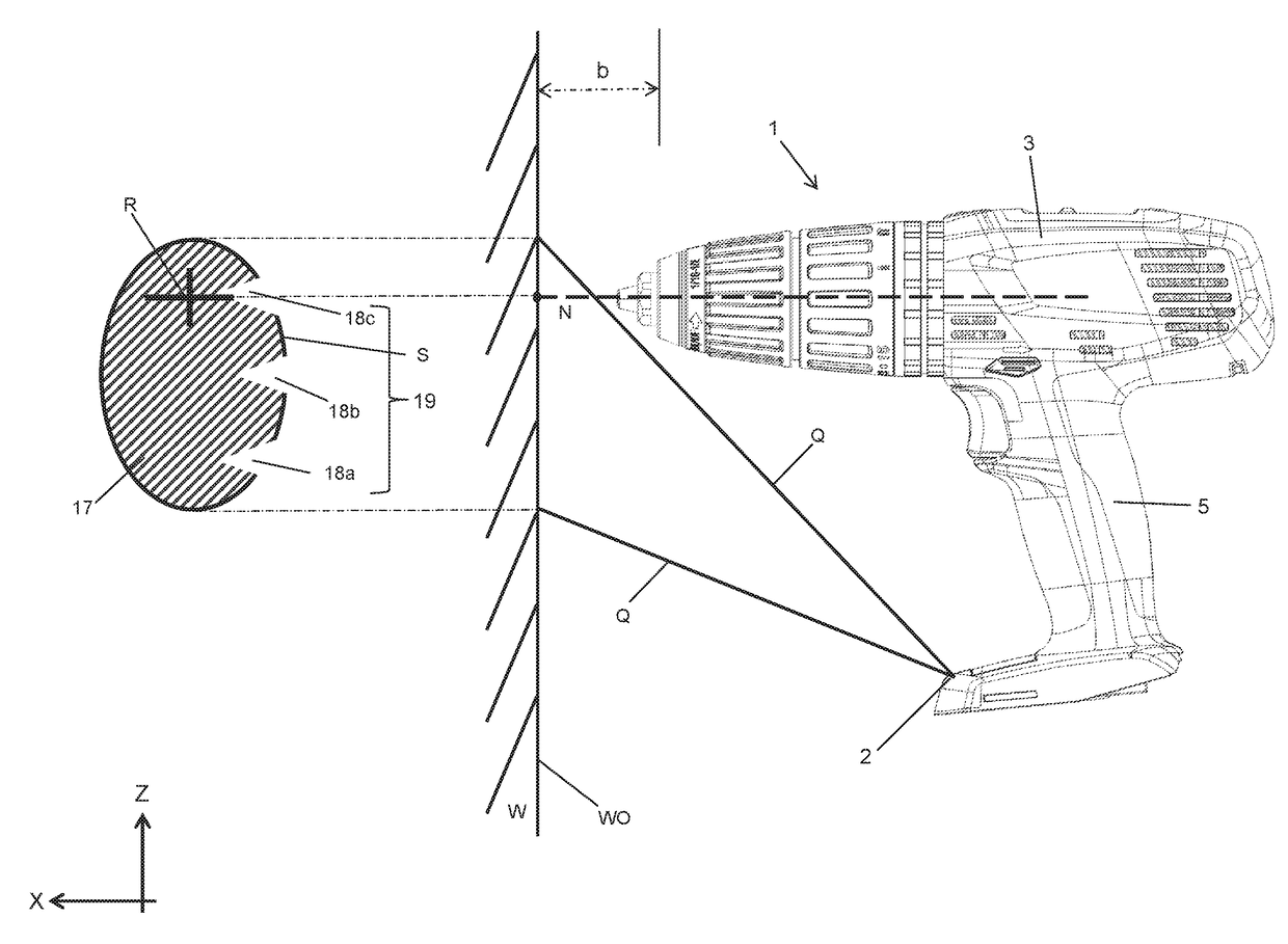
[0050]FIG. 12 shows a representation of the light spot 17 generated by the light source 9 on the workpiece surface WO according to a In this case the blocking elements 12a, 12b, 12c are in each case configured in the form of a cuboid with a trapezoidal base surface, so that the shadings 20 produced thereby in the light field 17 are illustrated in trapezoidal form.

third embodiment

[0051]FIG. 13 shows a representation of the light spot 17 generated by the light source 9 on the workpiece surface WO according to a In this case the blocking elements 12a, 12b, 12c are in each case configured in the form of a cuboid with a rectangular base surface, so that the shadings 21 produced thereby in the light field 17 are illustrated in rectangular form.

[0052]FIG. 14 shows a representation of the light spot 17 generated by the light source 9 on the workpiece surface WO according to a fourth embodiment. In this case the blocking elements 12a, 12b, 12c are in each case configured in the form of a cuboid with a rectangular base surface. In contrast to the third embodiment, however, according to the fourth embodiment the blocking elements 12a, 12b, 12c extend over the entire lens surface 16 of the light source 9, so that the shadings 22 produced thereby in the light field 17 are illustrated in lines.


PUM

PropertyMeasurementUnit
heightaaaaaaaaaa
heightaaaaaaaaaa
distancesaaaaaaaaaa

Abstract

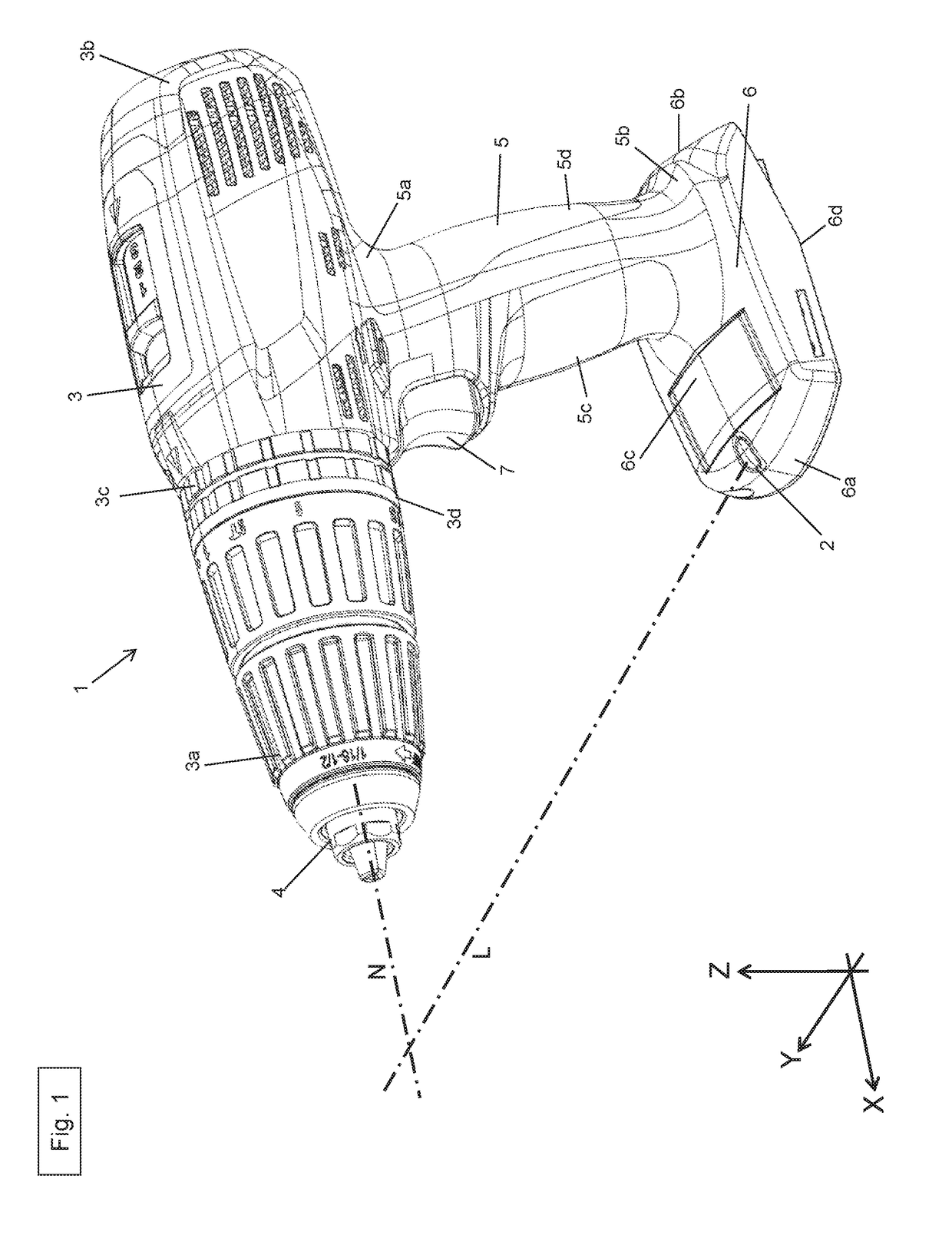
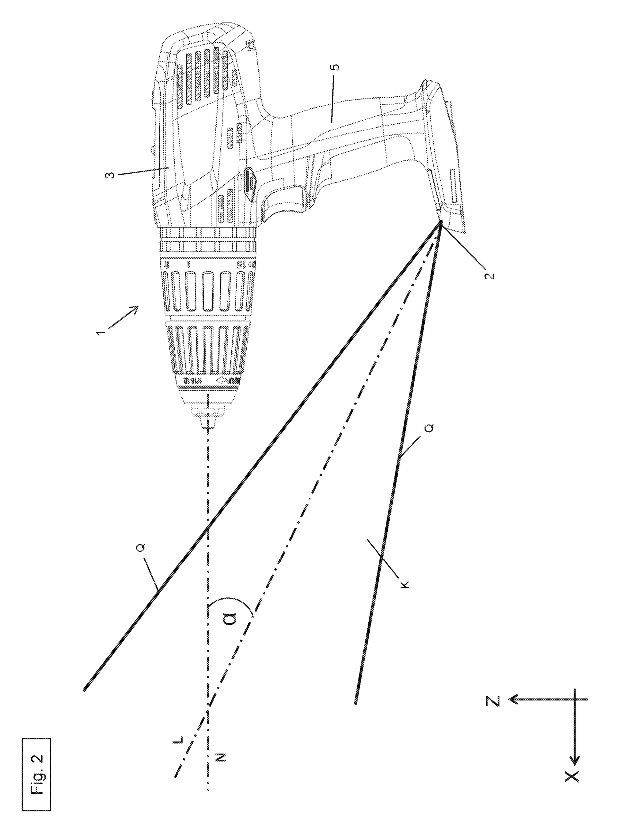
A device for determining a penetration depth in a drilled hole which is drilled into a workpiece (W) from a workpiece surface (WO) with a drill of a drilling machine. The device contains at least one light source for projecting a light field is provided onto a workpiece (W) to be processed by the drilling machine. The light source is positioned with respect to the drilling machine in such a way that a center axis (L) of the light source runs at an angle (a) with respect to a central axis (L) of the drilling machine, and at least a first blocking element for partially covering the light source is provided, said blocking element forming a reference on the light field.

Description

CROSS-REFERENCE TO RELATED APPLICATIONS[0001]This patent application is the U.S. National Stage of International Patent Application No. PCT / EP2015 / 071829, filed Sep. 23, 2015, which claims the benefit of European Patent Application No. 14190026.6, filed Oct. 23, 2014, which are each incorporated by reference.[0002]The present invention relates to a device for determining a penetration depth in a drilled hole which is drilled into a workpiece from a workpiece surface with a drill of a drilling machine, said device containing at least one light source for projecting a light field, for example, on a workpiece to be processed by the drilling machine.BACKGROUND OF THE INVENTION[0003]Devices for determining a penetration depth of a drill into a workpiece to be processed are widely used and known according to the prior art.[0004]Such devices can be configured relatively simply, for example, in the form of a straightedge which is adjustable in length and is arranged parallel to the drill of...

Claims


Application Information

Patent Timeline
Patent Type & Authority Patents(United States)
IPC IPC(8): G01N21/00B23Q17/24B25H1/00G01B11/22
CPCB23Q17/2428G01B11/22B25H1/0092B23Q17/2404B25F5/003B23Q17/2233B23Q17/2414
Inventor BAHR, DOMINIKZACHER, MARTIN
Owner HILTI AG
Learn More