Automatic transmission for hybrid vehicle and control method

Active Publication Date: 2019-04-02
PUNCH POWERGLIDE STRASBOURG
View PDF11 Cites 2 Cited by
  • Summary
  • Abstract
  • Description
  • Claims
  • Application Information

AI Technical Summary

Benefits of technology

The purpose of this patent is to offer an improvement over current solutions by using a less complicated construction and addressing the main drawbacks. This solution aims to provide a more efficient and effective solution.

Problems solved by technology

However, this first known solution has its drawbacks: for high electric motor powers (more than 40 kW, chiefly for plug-in vehicles, in other words rechargeable from an external source), it becomes difficult to integrate this motor in the gearbox, thus resulting in an increase in the overall size of the drivetrain.
The space constraints for placing the motor between the engine and the gearbox means that expensive motors with permanent magnets must be used.
Lastly, if the battery is flat and there is no more energy available to start the electric motor, a special starting system must be provided on the heat engine (such as a hydraulic torque converter or a friction clutch).
In other words, the resulting system occupies too much space, is too expensive and too complex for the performance provided.
By contrast, one major drawback lies in the extra weight and cost caused by using two electric motors, while only one is really used for the propulsion of the vehicle.
Nevertheless, these new developments in transmission specifically designed for hybrid vehicles also involve complex constructions, in particular requiring at least three planetary gear sets and at least four selective torque transmission devices (clutches or coupling mechanisms).
Moreover, these new developments do not allow a simple transition, in terms of construction, from a basic version, with more limited possibilities, to a more sophisticated version, with increased possibilities in terms of number of available gear ratios.

Method used


Image

  • Automatic transmission for hybrid vehicle and control method
  • Automatic transmission for hybrid vehicle and control method
  • Automatic transmission for hybrid vehicle and control method

Examples


Embodiment Construction

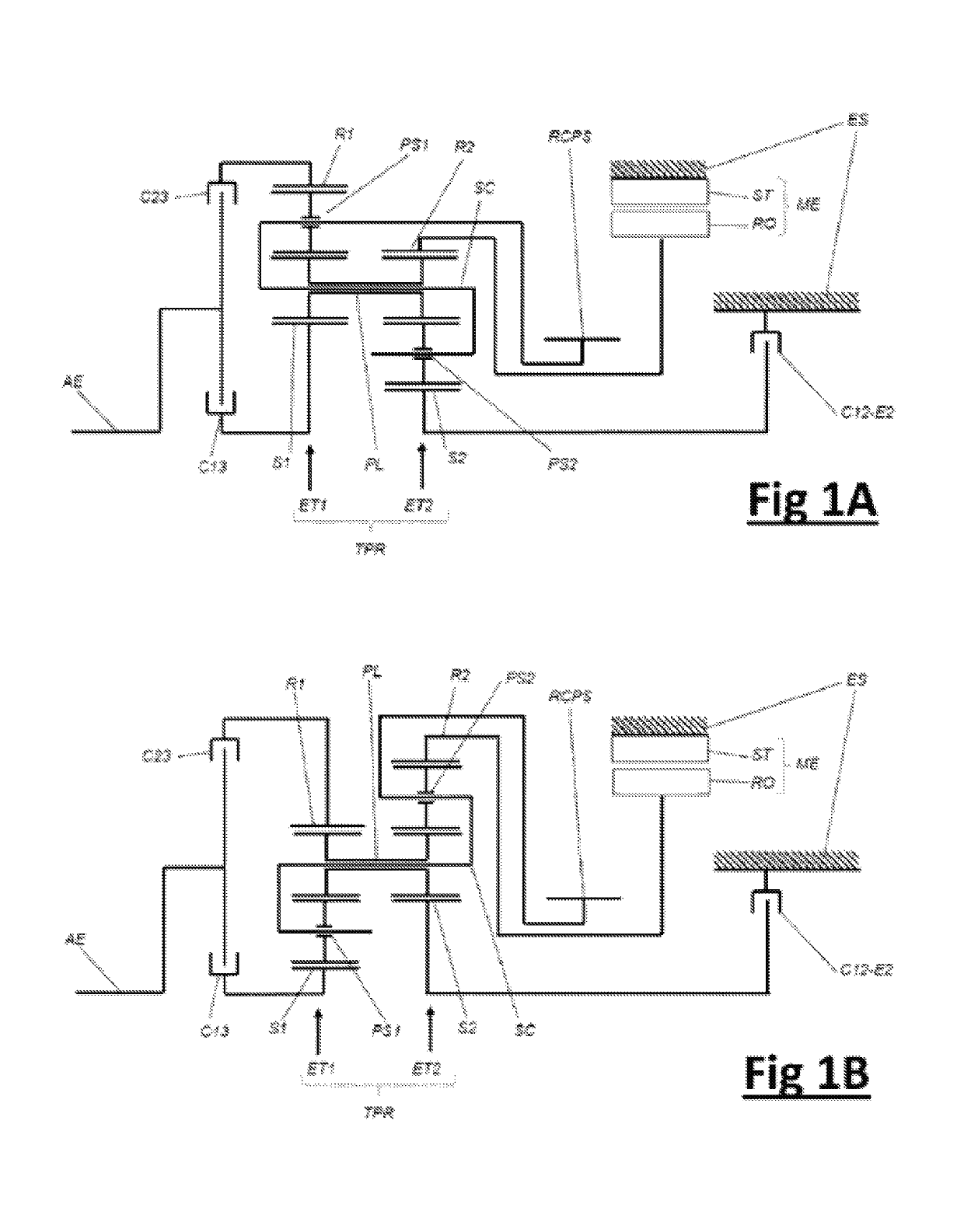
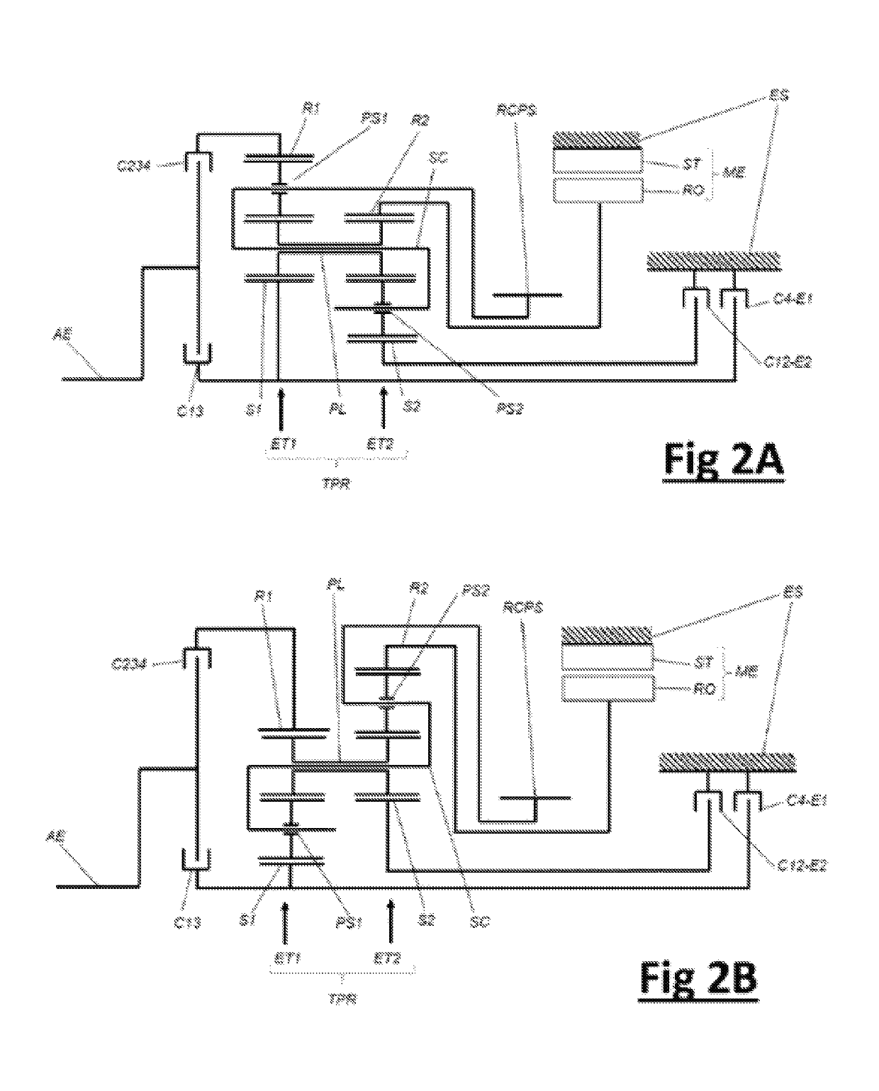
[0038]FIGS. 1 and 2 show an automatic transmission for a thermal-electric hybrid vehicle comprising:[0039]an input shaft (AE) driven by the heat engine;[0040]an output gear, ring gear or pinion (RCPS); a stationary element (ES), such as a casing;[0041]an electric motor (ME) in which the stator (ST) is connected to the stationary element (ES);[0042]at least the first, second and third selective torque transmission devices C13; C23 or C234; C12-E2, which can be engaged or activated selectively in order to establish, on the one hand, at least one gear ratio for driving a vehicle under the action of the electric motor (ME) operating as motor, on the other hand, two gear ratios for driving the vehicle under the action of the heat engine in the continuously variable speed mode (the electric motor (ME) then acting in generator mode and performing a rotating reaction) and, lastly, at least three gear ratios for driving the vehicle under the action of the heat engine (not shown).

[0043]Accord...


PUM


Abstract

An automatic transmission for a hybrid vehicle, includes: an input shaft (AE) driven by the heat engine; an output wheel, ring gear or pinion (RCPS); a stationary element (ES), such as a casing; an electric motor (ME) in which the stator (ST) is rigidly connected to the stationary element (ES); and at least first, second and third members for selective torque transmission (C13; C234; C12-E2), which can be engaged or activated selectively in order to establish different transmission ratios. The automatic transmission also includes a single Ravigneaux double planetary gear set (TPR) in which the functional elements that make up same are arranged in two stages of planetary gear sets (ET1 and ET2) connected by the aforementioned members to the input shaft (AE), to the rotor (RO) of the electric motor (ME) and to the stationary element (ES).

Description

BACKGROUND OF THE INVENTION[0001]The present invention concerns the field of equipment for motor vehicles, more particularly that of thermal-electric hybrid vehicles (comprising a heat engine, usually an internal combustion engine, and at least one electric motor) and relates to an automatic transmission, or automatic gearbox, optimized for such vehicles.[0002]The invention relates more specifically to transmissions for hybrid vehicles that can operate purely by electric drive, in other words for vehicles that can be moved solely by the action of an electric motor and in which the heat-engine and electric-motor drives pass through the same transmission before being applied to the driving wheels.[0003]For the above-mentioned type of vehicle, the state of the art currently offers two main types of architecture.[0004]A first type of architecture corresponds to so-called Type “P2” parallel hybrids, which operate with an electric motor placed between the heat engine and the gearbox. A sp...

Claims


Application Information

Patent Timeline
IPC IPC(8): F16H3/72F16H3/66B60K6/48B60K6/365F16H3/44
CPCF16H3/725B60K6/365B60K6/48F16H3/663B60K2006/4816B60Y2200/92Y10S903/918F16H2200/2005F16H2200/2025F16H2200/2038F16H2200/2041Y10S903/91F16H2003/445B60K6/547Y02T10/62
Inventor RIHN, MATTHIEUBRIDIER, CYRILLE
Owner PUNCH POWERGLIDE STRASBOURG
Why Eureka
Try Eureka