
Deflectable device with elongate actuator

Active Publication Date: 2019-05-23
KONINKLJIJKE PHILIPS NV
View PDF3 Cites 0 Cited by
  • Summary
  • Abstract
  • Description
  • Claims
  • Application Information

AI Technical Summary

Benefits of technology

The patent aims to create a deflectable device that has a simple construction.

Problems solved by technology

Device maneuverability has a strong influence on both the procedure time (and therefore also X-ray doses and cost) as well as the risk of complications such as perforation.
However, conventional devices are often difficult to maneuver and control, for the following reasons:
The contact friction between the device and vessels may cause stick-slip phenomena, leading to hysteresis and sudden jumps in tip movement, with reduced control of the tip as a consequence.
Hence, some locations are unreachable or are only reached after a lengthy procedure.
Therefore, in order to reach the desired location, surgeons often have to use trial-and-error to choose the device with the correct stiffness and distal shape.
Again, such device replacements lead to extended operating times, with accompanying increase of X-ray and contrast agent doses.
In addition, the repeated extraction and insertion can do serious harm to the patient and increase the risk of infection.
Steerable catheters based on shape memory alloy steering have potentially lower shaft stiffness.
However, integration of shape memory alloy actuators in catheters (or guidewires) is complex.

Method used


Image

  • Deflectable device with elongate actuator
  • Deflectable device with elongate actuator
  • Deflectable device with elongate actuator

Examples


Embodiment Construction

[0048]The present invention will be described with respect to particular embodiments and with reference to certain drawings but the invention is not limited thereto but only by the claims. The drawings described are only schematic and are non-limiting. In the drawings, the size of some of the elements may be exaggerated and not drawn on scale for illustrative purposes. The dimensions and the relative dimensions do not correspond to actual reductions to practice of the invention.

[0049]The terms first, second and the like in the description and in the claims, are used for distinguishing between similar elements and not necessarily for describing a sequence, either temporally, spatially, in ranking or in any other manner. It is to be understood that the terms so used are interchangeable under appropriate circumstances and that the embodiments of the invention described herein are capable of operation in other sequences than described or illustrated herein.

[0050]It is to be noticed that...


PUM


Abstract

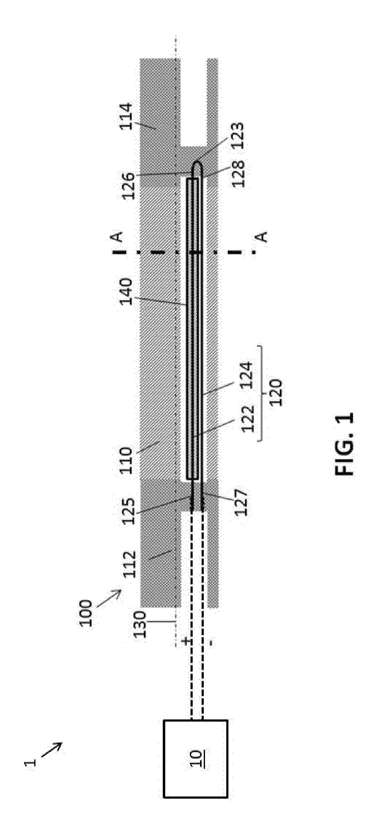
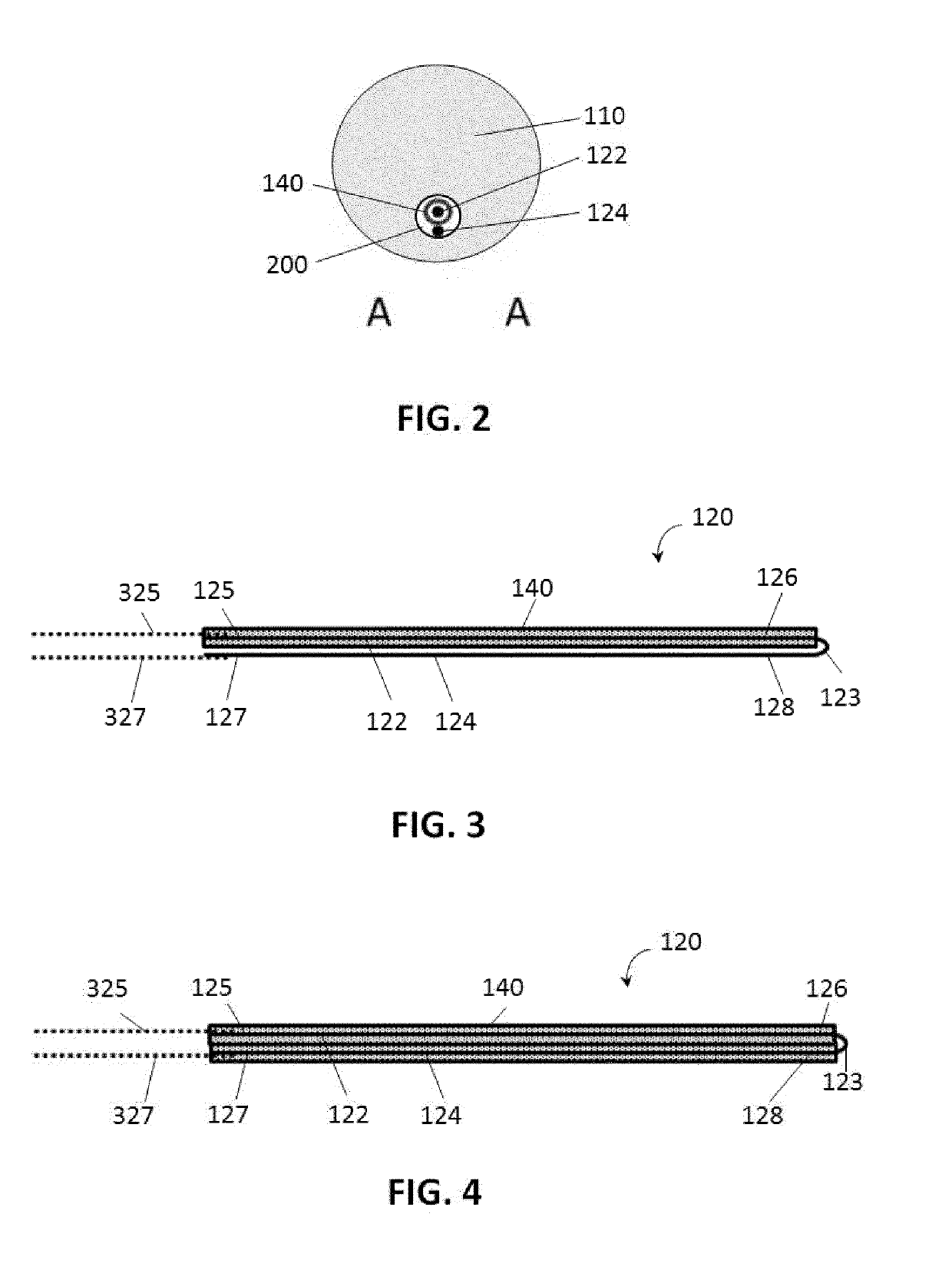
A deflectable device (100) comprising an elongate body (110) and a folded elongate member (120) is configured to change an orientation of the distal portion (114) of the elongate body (110) with respect to the proximal portion (112) of the elongate body (110) upon an electrical current flowing through the folded elongate member (120) causing a change of a length of the folded elongate member (120).

Description

FIELD OF THE INVENTION[0001]The present invention relates to the field of deflectable devices. More specifically it relates to deflectable devices steered by application of an electrical current.BACKGROUND OF THE INVENTION[0002]Minimally Invasive Vascular Surgery (MIVS) is widely adopted and often preferred above open surgery for its smaller incisions, less blood loss, reduced risk of infection, decreased pain and quicker recovery. Within this field, various surgeries are performed using minimally invasive instruments such as catheters, sheaths, and guidewires, under fluoroscopic guidance.[0003]Device maneuverability has a strong influence on both the procedure time (and therefore also X-ray doses and cost) as well as the risk of complications such as perforation. However, conventional devices are often difficult to maneuver and control, for the following reasons:[0004]The contact friction between the device and vessels may cause stick-slip phenomena, leading to hysteresis and sudde...

Claims


Application Information

Patent Timeline
IPC IPC(8): A61M25/01
CPCA61M25/0158A61M2025/09141A61B1/00147A61M2205/0266
Inventor DE HAAS, CORNELIS GERARDUS MARIAVAN BEEK, JOHANNUS GERARDUSVONCKEN, RUDOLF MARIA JOZEFHAARTSEN, JACOB ROGERVAN DER LINDE, FRANCISCUS REINIER ANTONIUSHAKKENS, FRANCISCUS JOHANNES GERARDUS
Owner KONINKLJIJKE PHILIPS NV
Learn More