Control device for vehicle drive device
a control device and driving device technology, applied in the direction of vehicle position/course/altitude control, process and machine control, instruments, etc., can solve the problems of large amount of heat generated, reduce energy efficiency, and the kinetic energy during the shifting cannot be collected, so as to achieve reliable and easy determination
- Summary
- Abstract
- Description
- Claims
- Application Information
AI Technical Summary
Benefits of technology
Problems solved by technology
Method used
Image
Examples
first embodiment
Schematic Configuration of Hybrid Drive Device
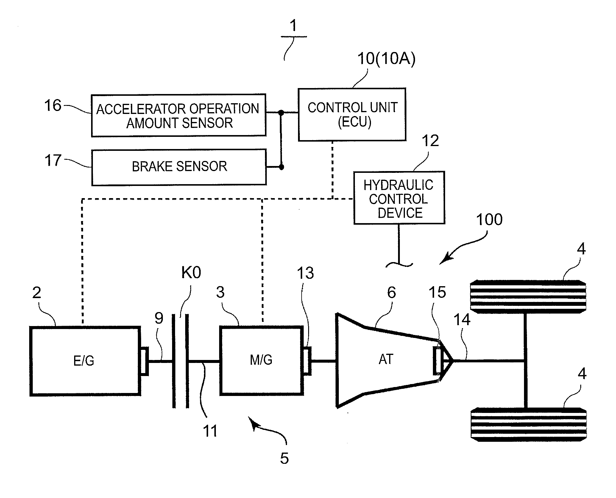
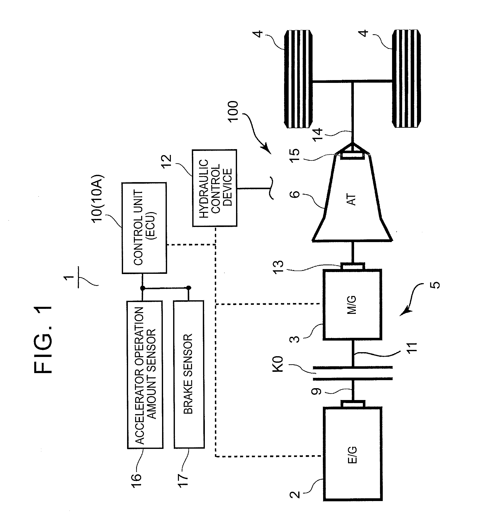
[0042]As shown in FIGS. 1 and 2, a hybrid vehicle (hereinafter simply referred to as the “vehicle”) 1 has a rotating electrical machine (hereinafter referred to as the “moor generator” or simply as the “motor”) 3 in addition to an internal combustion engine 2 as a driving source. A hybrid drive device 100 as a vehicle drive device forming a power train of the vehicle 1 is a one-motor hybrid drive device, and has a speed change mechanism 6 provided on a transmission path between the internal combustion engine 2 and wheels 4, and an input portion 5 located between the speed change mechanism 6 and the internal combustion engine 2.
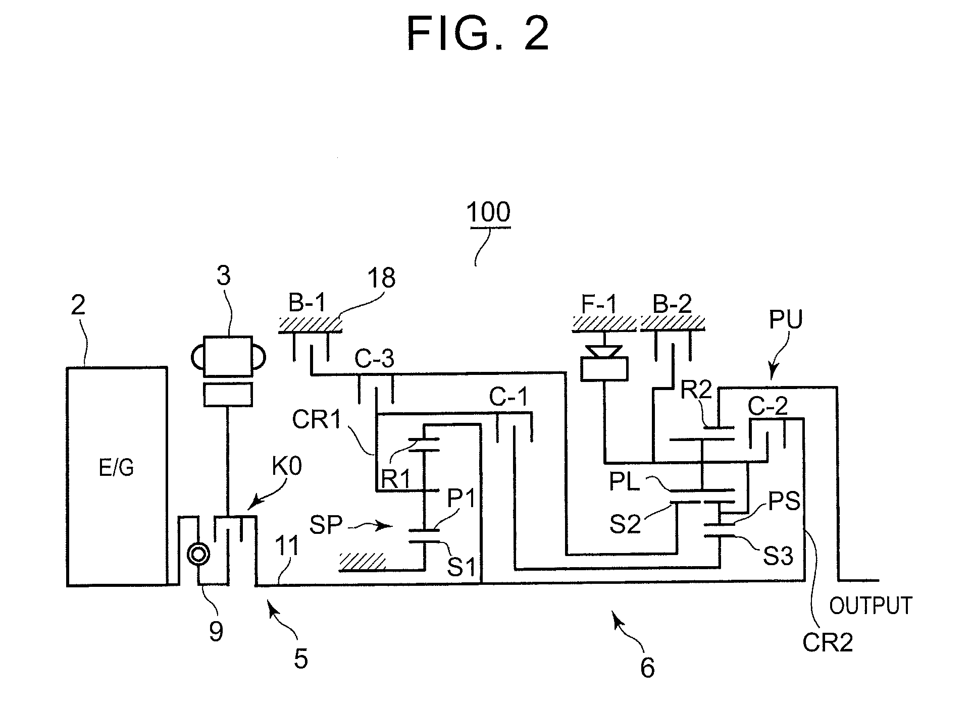
[0043]As shown in FIG. 2, the speed change mechanism 6 has a plurality of engagement elements (more specifically, a plurality of friction engagement elements) C-1 to C-3, B-1, B-2, and F-1, and is formed by a multi-stage automatic transmission (stepped automatic transmission) that attain a plurality of shift speeds...
second embodiment
[0090]A vehicle control device according to a second embodiment will be described with reference to FIGS. 9 to 11. The second embodiment is different from the first embodiment in that an estimated temperature of the friction engagement element during shifting is obtained, and whether a skip shift can be performed or not is determined based also on whether the estimated temperature is higher than an allowable temperature or not. Only the difference from the first embodiment will be described below, and description of similar portions will be omitted.
[0091]FIG. 9 is a diagram showing how an estimated temperature of the active friction engagement element changes during traveling of the vehicle. FIG. 9 shows that the engagement / disengagement state of the active friction engagement element is changed between time t1 and t2 and between time t3 and t4, and that the active friction engagement element generates heat and increases in temperature during shifting as it makes slip rotation while...
third embodiment
[0099]In the second embodiment, whether a jumping shift can be performed or not is determined based on all of the requirement liter the amount of heat generation, the requirement for the estimated temperature, and the requirement for the shift time. However, whether a jumping shift can be performed or not can be determined based only on, e.g., the requirement for the amount of heat generation. Alternatively, whether a jumping shift can be performed or not can be determined based only on the requirement for the estimated temperature, or whether a jumping shift can be performed or not can be determined based only on the requirement for the amount of heat generation and the requirement for the estimated temperature.
[0100]In the first to third embodiments, a hybrid drive device is described as an example of the vehicle drive device. However, an engine is not necessarily required as a driving source, and the present embodiment is applicable to any vehicle drive device that includes a rot...
PUM
 Abstract
Description
Claims
Application Information
 - R&D
- Intellectual Property
- Life Sciences
- Materials
- Tech Scout
- Unparalleled Data Quality
- Higher Quality Content
- 60% Fewer Hallucinations
Browse by: Latest US Patents, China's latest patents, Technical Efficacy Thesaurus, Application Domain, Technology Topic, Popular Technical Reports.
© 2025 PatSnap. All rights reserved.Legal|Privacy policy|Modern Slavery Act Transparency Statement|Sitemap|About US| Contact US: help@patsnap.com


