
Method for recovering process wastewater from a steam power plant

a technology of water treatment and process wastewater, which is applied in the direction of water/sewage treatment by ion exchange, machines/engines, lighting and heating apparatus, etc., can solve the problems of process wastewater, process wastewater, and various contaminants that may be introduced into the working medium, so as to reduce the volume of diw which has to be provided by the deionization plant, the service life of the condensate purification plant is reduced, and the ion loading is higher

Active Publication Date: 2015-09-10
SIEMENS ENERGY GLOBAL GMBH & CO KG
View PDF1 Cites 4 Cited by
  • Summary
  • Abstract
  • Description
  • Claims
  • Application Information

AI Technical Summary

Benefits of technology

This patent relates to a method to operate a steam power plant in a more resource-efficient way. It aims to minimize the wastewater treatment plant and the use of freshwater, as well as the costs associated with deionization. The method involves separating and collecting process wastewaters from the plant, forming different sub-volumes based on their level of contamination. The recirculated wastewaters are then cooled and returned to the plant using a combination of existing infrastructure. This leads to less consumption of chemicals and a more environmentally-friendly power plant.

Problems solved by technology

During the energy generation process various contaminants may be introduced into the working medium.
Moreover, process wastewaters arise due to continuous sampling and leaks in the water-steam circuit.
Backwashing and regeneration processes in the deionization plant and condensate purification also result in process wastewater.
A disadvantage here, however, is that all the contaminants are passed from one pressure level to the next.
However, no method has hitherto been known from the prior art by which all the process wastewaters from a power plant can be collected and largely completely re-used in the water-steam circuit.
These plants for providing demineralized water produce a process wastewater which is relatively heavily contaminated.
The process wastewaters from the evacuation system and from sampling are relatively lightly contaminated, but do contain ammonia.

Method used


Image

  • Method for recovering process wastewater from a steam power plant
  • Method for recovering process wastewater from a steam power plant
  • Method for recovering process wastewater from a steam power plant

Examples


Embodiment Construction

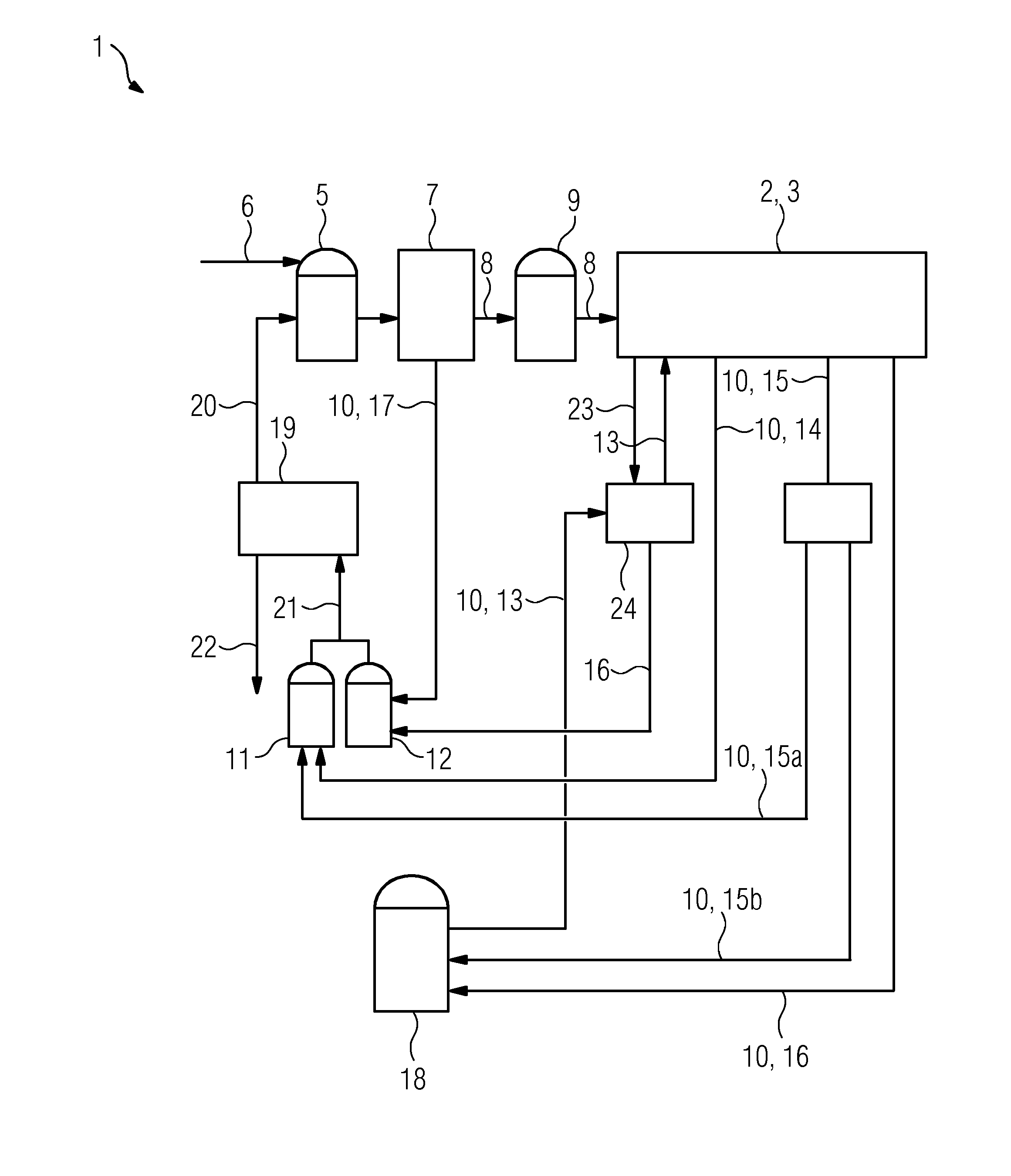
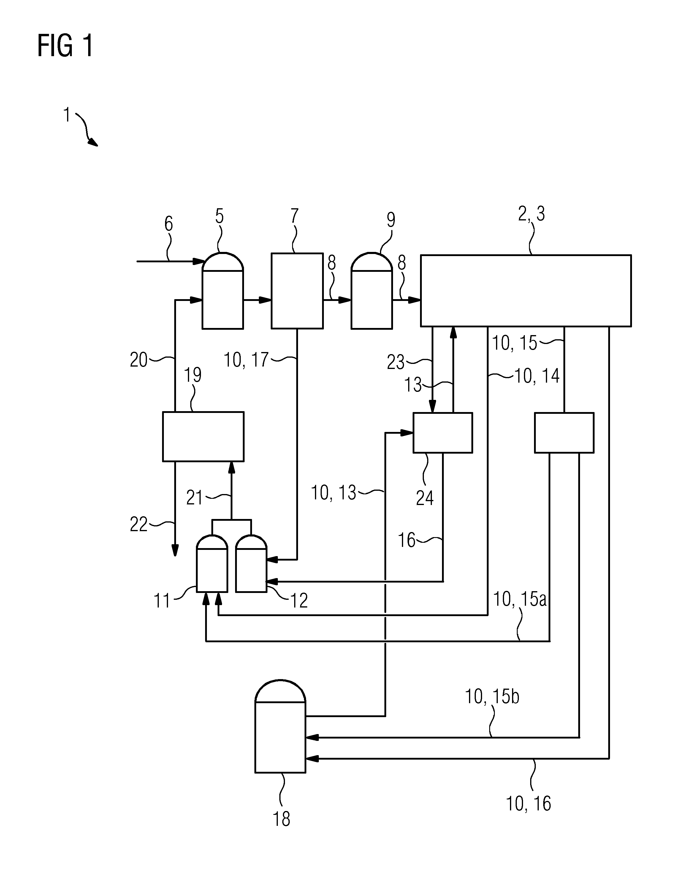
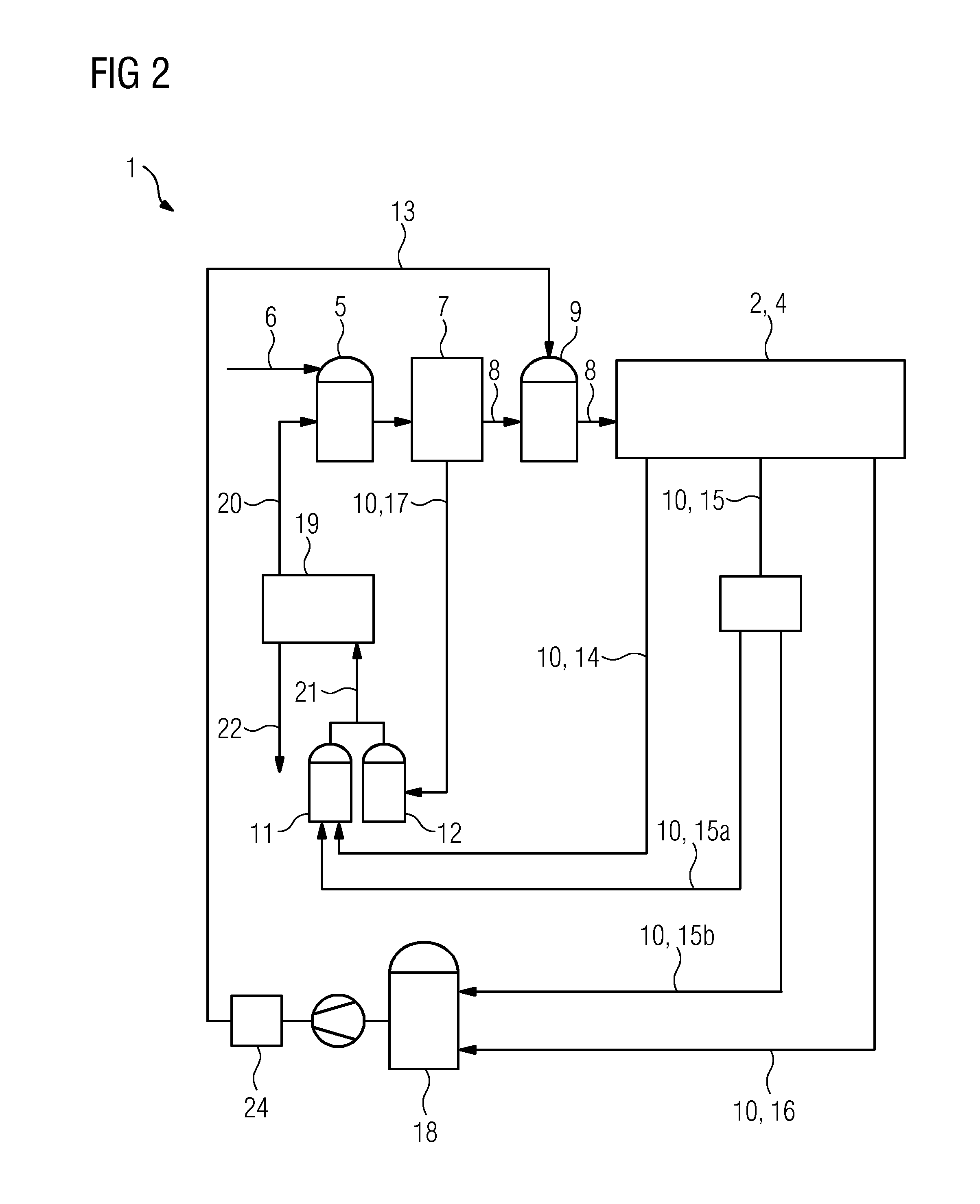
[0038]FIG. 1 shows a steam power plant 1 with a water-steam circuit 2. The water-steam circuit 2 is shown only diagrammatically here. The water-steam circuit 2 comprises a once-through boiler 3 not shown in any greater detail here, in which steam is generated, a steam turbine and a condenser. For startup and shutdown of the steam power plant 1, the condenser additionally comprises an evacuation system, by which a vacuum can be established.

[0039]The steam power plant 1 further comprises a raw water tank 5, which is supplied with water from a fresh water source via a raw water line 6. Continuous replenishing with water is necessary, since water is continuously being lost from the system through leaks.

[0040]The raw water tank 5 is connected to a demineralization plant 7 (deionization plant) via a line. The demineralization plant 7 comprises ion exchangers (ion exchange resins), by which the raw water from the raw water tank 5 is deionized, resulting in demineralized water 8. In additio...


PUM

PropertyMeasurementUnit
volumeaaaaaaaaaa
conductivityaaaaaaaaaa
energyaaaaaaaaaa

Abstract

A method for operating a steam power plant having a water-steam circuit, according to which method the process wastewater produced is collected from the water-steam circuit, in a separated manner according to the degree of contamination thereof, in a number of partial wastewater quantities is provided. At least a first partial wastewater quantity having a first degree of contamination and at least a second partial wastewater quantity having a second degree of contamination are formed in the process. The second degree of contamination is higher than the first degree of contamination. The first partial wastewater quantity and the second partial wastewater quantity are mixed together in such a manner that a combined process wastewater is produced, which is fed to a wastewater treatment plant.

Description

CROSS-REFERENCE TO RELATED APPLICATIONS[0001]This application claims priority to PCT Application No. PCT / EP2013 / 069095 having a filing date of Sep. 16, 2013, based off of DE102012217717.5 having a filing date of Sep. 28, 2012, the entire contents of which are hereby incorporated by reference.FIELD OF TECHNOLOGY[0002]The following relates to a method for operating a steam power plant with a closed water-steam circuit and a reprocessing facility for process water and in particular the recovery of process water from wastewater from the water-steam circuit.BACKGROUND[0003]Steam power plants serve to generate electrical energy. They may take the form of thermal power plants, wherein the steam is generated using a fossil fuel-fired boiler. A thermal power plant substantially comprises in this case, in addition to the fired boiler, a steam turbine, a water-steam circuit and a condenser.[0004]Steam power plants may likewise take the form of combined cycle gas turbine (CCGT) plants. Such com...

Claims


Application Information

Patent Timeline
Patent Type & Authority Applications(United States)
IPC IPC(8): B01F3/08B01F15/06
CPCB01F3/0803B01F3/088B01F2015/062B01F2003/0884B01F15/06C02F1/048C02F1/42F01K13/00F01K19/00F22B37/48F22D11/006C02F2209/05Y02W10/37B01F23/405B01F23/49B01F35/90B01F23/48B01F2035/99
Inventor AMSLINGER, UTEFLEISCHMANN, FRANZISKAGLUCK, WOLFGANGSATTELBERGER, MARCSPIES, WERNERSOLLNER, ANKEWIDMANN, PETER
Owner SIEMENS ENERGY GLOBAL GMBH & CO KG
Learn More