
Connection terminal

a terminal and connection technology, applied in the field of connection terminals, can solve the problems of complex parts management, increased production cost, and hardly obtained mechanical strength, and achieve the effects of reducing the types of press dies, reducing the number of presses, and suppressing the thermal deformation generated in the terminal body

Inactive Publication Date: 2015-08-27
YAZAKI CORP
View PDF38 Cites 7 Cited by
  • Summary
  • Abstract
  • Description
  • Claims
  • Application Information

AI Technical Summary

Benefits of technology

The present invention is designed to reduce the number of press dies required, make terminal parts more common, and improve the mechanical strength of the connection terminal. The invention achieves this by creating a wraparound configuration part that wraps around the box part of the terminal, which increases the fixed strength of the functional configuration part without requiring any changes to the box part. The functional configuration part is made of resin material, which has a lower melting temperature than metal, which helps to prevent thermal deformation. Overall, this design allows for a more efficient manufacturing process and improved performance of the connection terminal.

Problems solved by technology

Accordingly, many press dies need to be manufactured for a blanking or stamping work or a bending work in accordance with many kinds of terminals, so that a production cost is increased.
Further, management of parts is complicated because many kinds of terminals exist.
Further, in the functional configuration part formed by an embossing work of press metal, a mechanical strength may be hardly obtained.
Especially, in the case of a microscopic terminal, it is difficult to ensure the mechanical strength of the functional configuration part.

Method used


Image

  • Connection terminal
  • Connection terminal
  • Connection terminal

Examples


Embodiment Construction

[0032]Now, exemplary embodiments of the present invention will be described below by referring to the drawings.

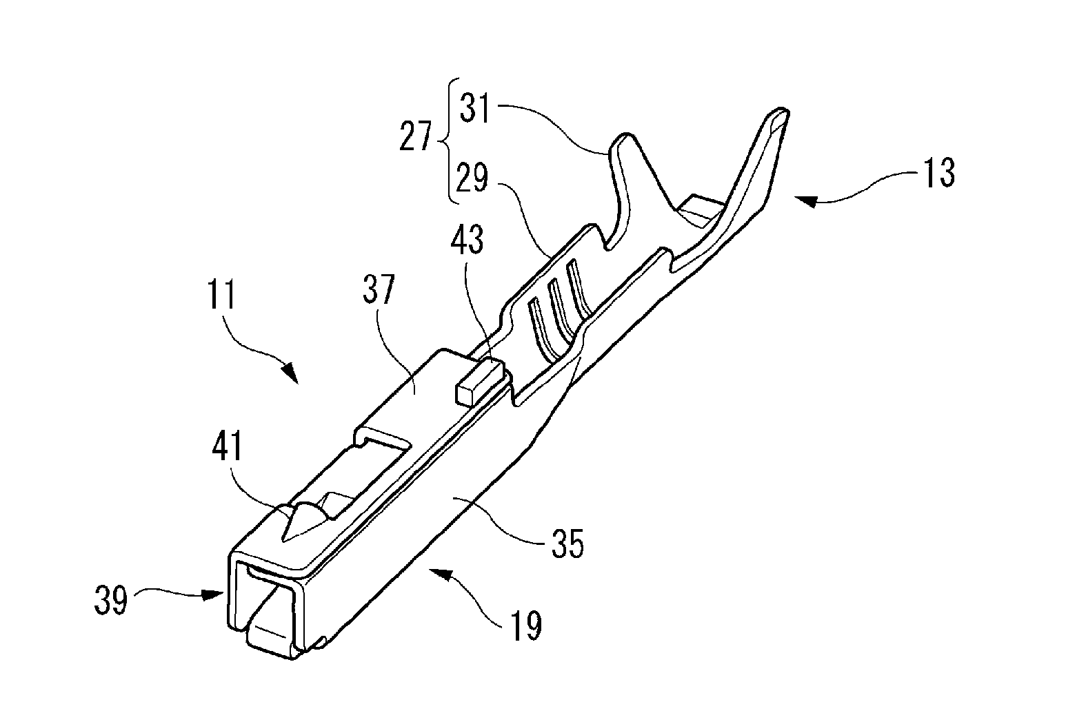
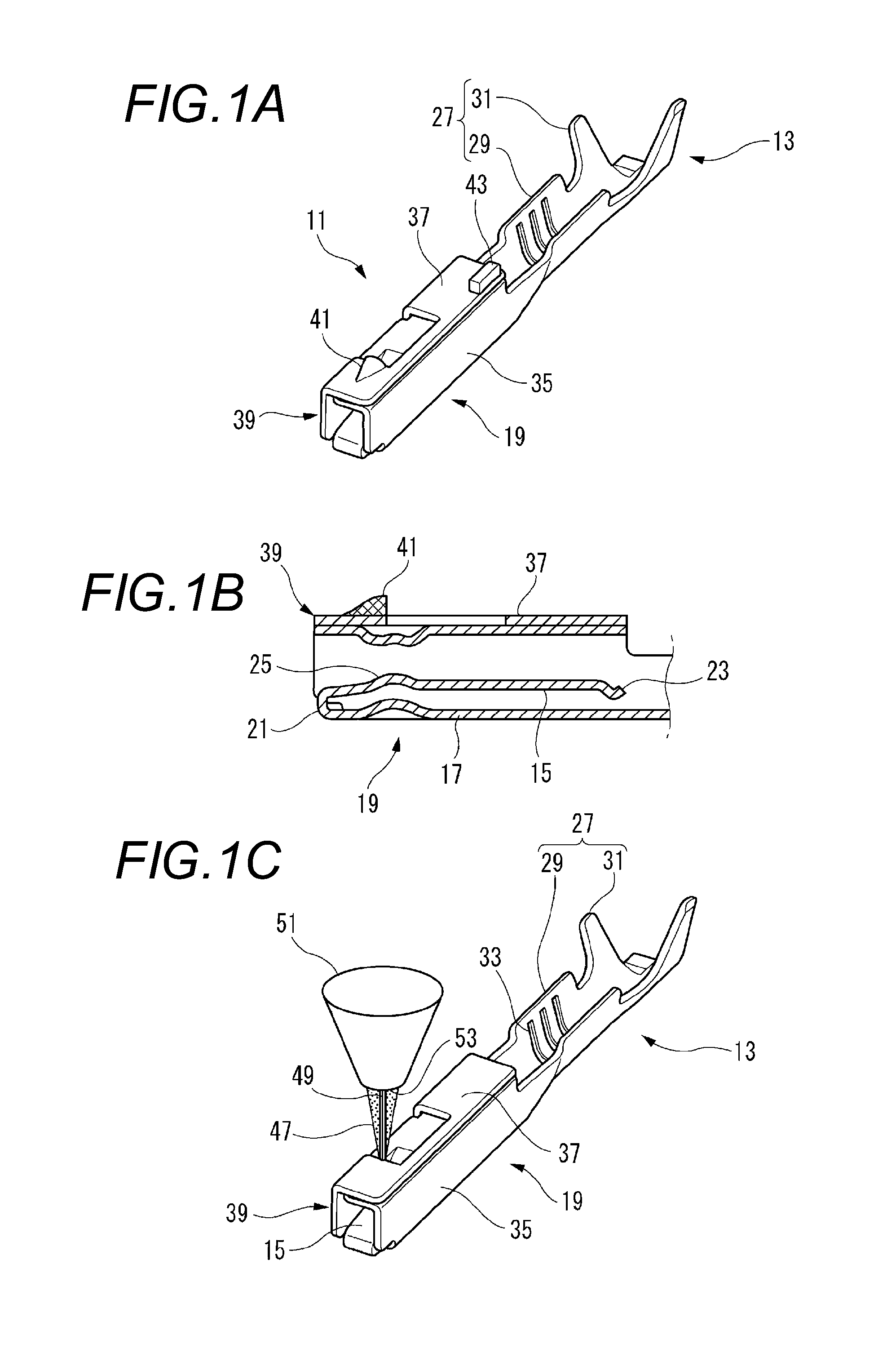
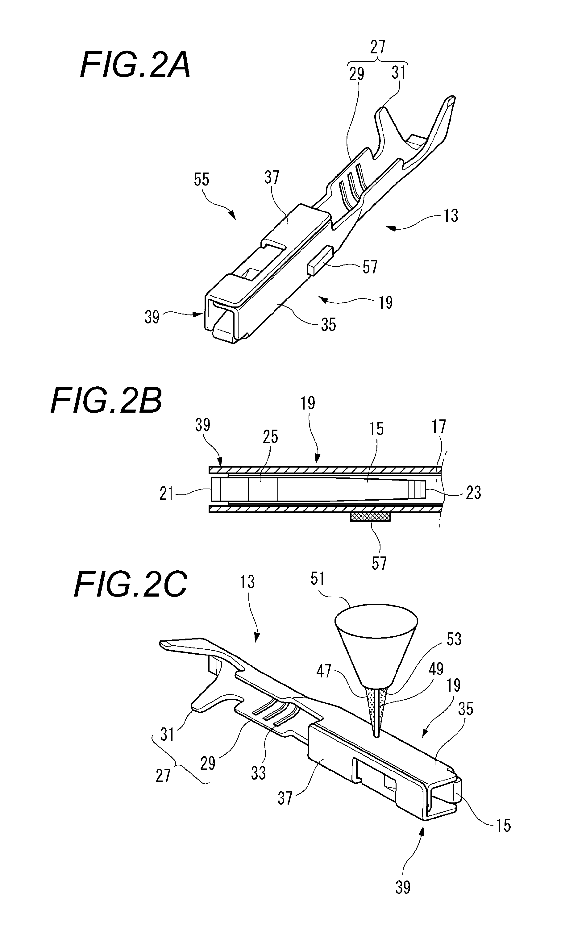
[0033]A connection terminal 11 according to a first exemplary embodiment of the present invention is formed with electrically conductive metal and used to be attached to, for instance, a connector housing (not shown in the drawing). The connection terminal 11 includes, as shown in FIG. 1A, a terminal body 13 that has a terminal-connect part 19 provided with a tubular box part 39 having an opening in one end side (the left side in the drawing) into which a mating terminal (not shown in the drawing) is inserted and a conductor-connect part 27 formed in the other end side (the right side in the drawing) of the terminal-connect part 19, which are integrally formed by a press work. The connection terminal 11 also includes a lance-engage part 41 and an insertion guide part 43 as functional configuration parts protruding from and integrally formed with the box part 39 by a solid m...


PUM


Abstract

A connection terminal includes a terminal body that includes a terminal-connect part provided with a tubular box part having an opening in one end side into which a mating terminal is inserted and a conductor-connect part formed in the other end side of the terminal-connect part. The terminal-connect part and the conductor-connect part are formed integrally by a press work. A functional configuration part is allowed to protrude from and integrally formed with the box part by solid modeling.

Description

CROSS REFERENCE TO RELATED APPLICATIONS[0001]This application is based upon and claims the benefit of priority of Japanese Patent Application No. 2014-034493 filed on Feb. 25, 2014, the contents of which are incorporated herein by reference in its entirety.BACKGROUND OF THE INVENTION[0002]1. Field of the Invention[0003]The present invention relates to a connection terminal.[0004]2. Description of the Related Art[0005]In a connection terminal used for, for instance, an electrical equipment of a motor vehicle, various functional configuration parts are formed. For instance, in a female terminal fitting disclosed in JP-A-2003-243076, the functional configuration part having a reverse-insertion preventing function is provided.[0006]As shown in FIG. 6A, in the female terminal fitting 501, in an upper wall 505 of an electric contact part 503, a guide groove 507 as the functional configuration part which is recessed inward is formed along an axial direction. Thus, the upper wall 505 of the...

Claims


Application Information

Patent Timeline
Patent Type & Authority Applications(United States)
IPC IPC(8): H01R13/627H01R4/20H01R13/629
CPCH01R13/6272H01R4/20H01R13/629H01R4/185H01R13/113H01R13/41H01R43/16
Inventor MIYAKAWA, DAISUKE
Owner YAZAKI CORP
Learn More