
Automated roof runoff management system

a runoff management system and automatic technology, applied in the field of automatic roof runoff management system, can solve the problems of combined sewer overflow (cso), untreated combination of storm water and effluence overflow, and stream degradation

Inactive Publication Date: 2015-08-06
RAINBANK
View PDF6 Cites 10 Cited by
  • Summary
  • Abstract
  • Description
  • Claims
  • Application Information

AI Technical Summary

Benefits of technology

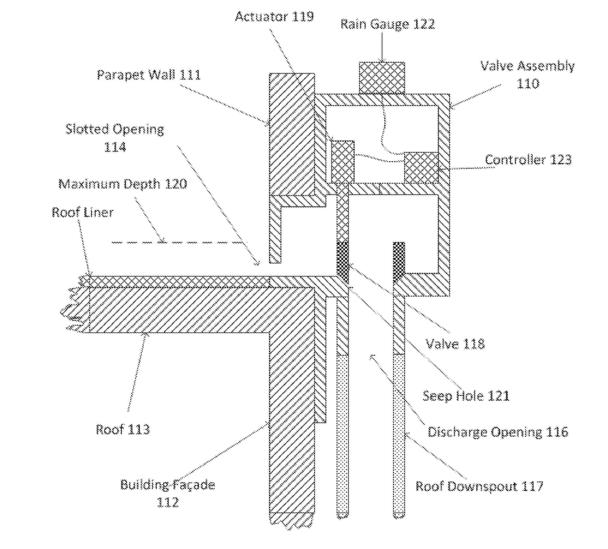
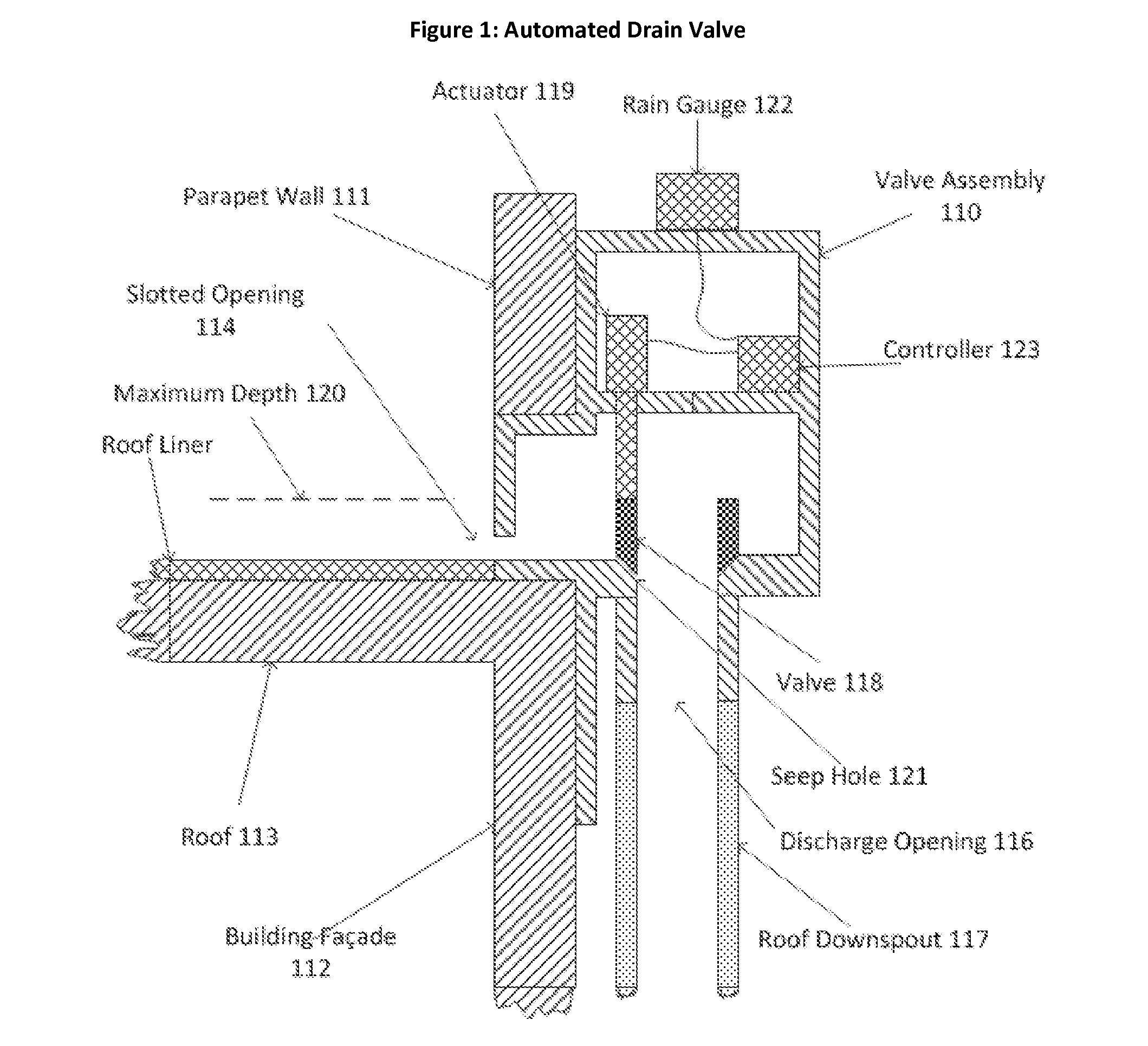
The invention is a new valve that can hold water on a roof or other surface and be controlled by a computer to release the water at a later time. This valve helps keep the underground storm water system from becoming overwhelmed with water during heavy rains. The computer uses information from sensors to determine the best time to open or close the valve, based on weather forecasts and other data. The valve can be placed on a roof drain or scupper to control the flow of water into the main drain. This technology helps manage heavy rainfall and ensures the proper function of the storm water system.

Problems solved by technology

The high concentration of impervious area and undersized storm water systems in older cities, such as New York, Philadelphia, Washington D.C., causes several problems 1) pollution from sewage overflows and other contaminants 2) stream degradation and 3) flooding.
During storm events, runoff from impervious surfaces such as roofs and pavement causes the storm water system to overflow into the wastewater sewer system, and vice versa, which result in combined sewer overflows (CSO).
That is, when the system is overloaded, the untreated combination of storm water and effluence overflows directly into the local waterways.
This increase in regulation translates into increased costs for developers and, in some municipalities, all property owners.
All of these systems represent an increased cost for proposed development and substantial costs to existing buildings.

Method used


Image

  • Automated roof runoff management system
  • Automated roof runoff management system
  • Automated roof runoff management system

Examples


third embodiment

Operation

[0044]In this embodiment different rooftop runoff management systems 901 may open or close valves 304 at different times than other rooftop management systems 901, in order to optimize runoff across the entire municipality.

[0045]If a rooftop runoff management system 901 is unable to communicate with central server 904 it will operate as described in embodiment 2.

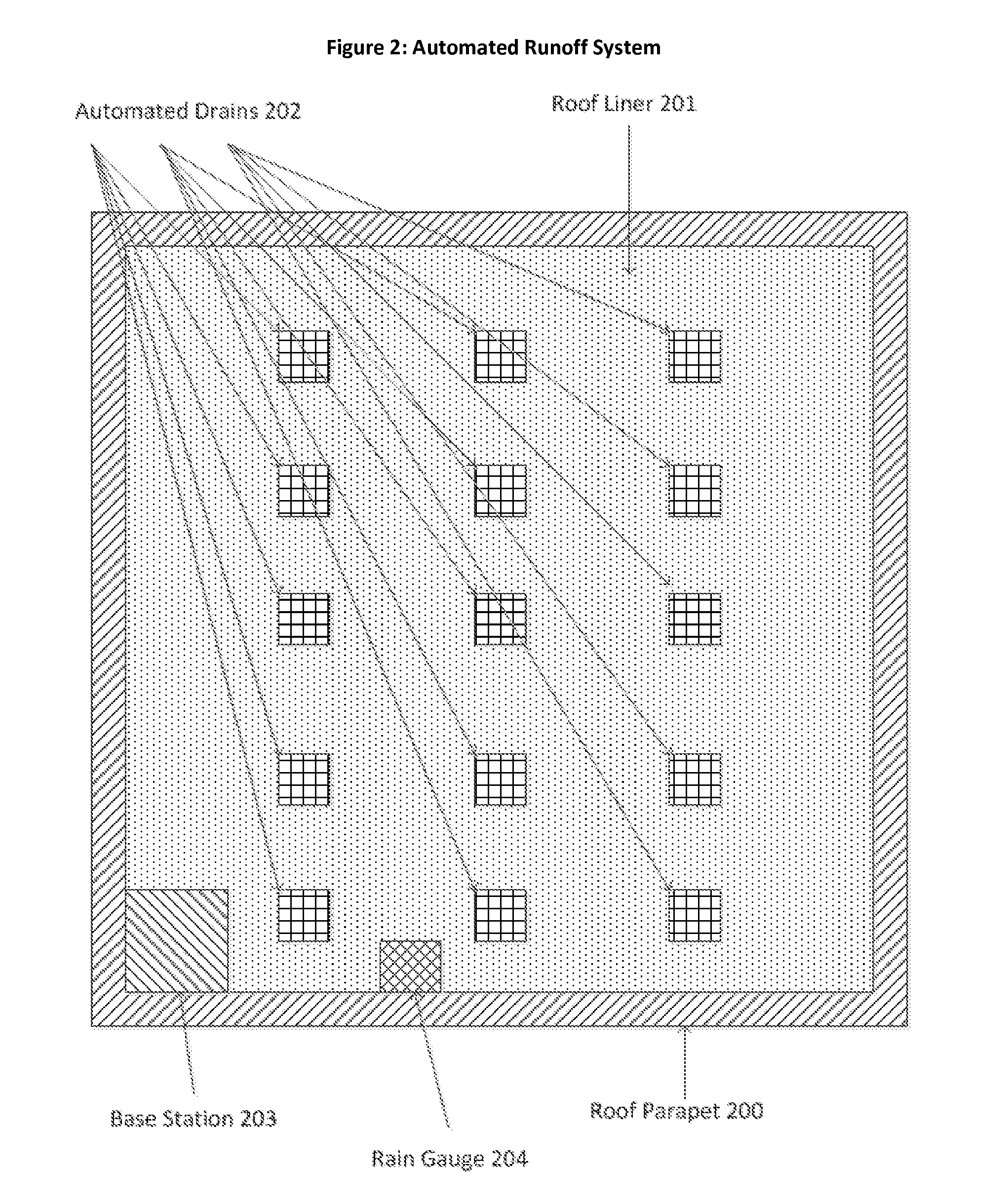
[0046]If a rooftop management system 901 is capable of communicating with central server 904 the selection of times when to open valves 304 in the rooftop runoff management system 901 is determined by the central server based on valve 304 status, depth sensor 307 status and rain gauge 204 status from the plurality of rooftop management systems 901. For example, regulation may only allow a subset of the plurality of rooftop management system 901 s to discharge concurrently.


PUM


Abstract

The Automated Roof Runoff Management System mitigates the impact of storm water overwhelming existing infrastructure to handle it by automatically retaining storm water on roofs and releasing it at times where the system has adequate capacity to handle the retained water.

Description

TECHNICAL FIELD AND INDUSTRIAL APPLICABILITY OF THE INVENTION[0001]This invention relates to the collection and release of water from a building roof, and more specifically relates to a novel valve and control system therefore to deliver such water from the roof in a controlled manner.BACKGROUND OF THE INVENTION[0002]The growth of cities has increased reliance on undersized storm water conveyance systems. The high concentration of impervious area and undersized storm water systems in older cities, such as New York, Philadelphia, Washington D.C., causes several problems 1) pollution from sewage overflows and other contaminants 2) stream degradation and 3) flooding. In many cities the storm water system shares infrastructure with the sanitary sewer in what is called a combined sewer system. During storm events, runoff from impervious surfaces such as roofs and pavement causes the storm water system to overflow into the wastewater sewer system, and vice versa, which result in combined ...

Claims


Application Information

Patent Timeline
IPC IPC(8): E03C1/122G01W1/14G06F9/44
CPCE03C1/122G01W1/14G06F9/44E03F5/107E04D2013/0427E04D13/0409E04D13/0431Y10T137/6969
Inventor SHAPIRO, MICAH ETHANBERG-SONNE, ANKERDUTT, KEVIN CHARLESEGGLESTON, JOHN RANDOLPH
Owner RAINBANK
Learn More