Sulfide solid electrolyte
a solid electrolyte, sulfide technology, applied in the direction of electrochemical generators, non-aqueous electrolyte cells, non-metal conductors, etc., to achieve the effect of reducing the decomposition potential
- Summary
- Abstract
- Description
- Claims
- Application Information
AI Technical Summary
Benefits of technology
Problems solved by technology
Method used
Image
Examples
example 1
Synthesis of Electrolyte
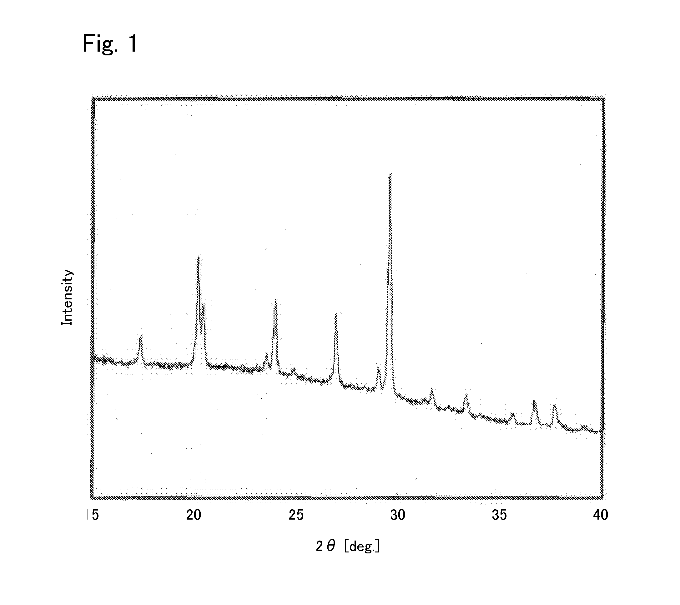
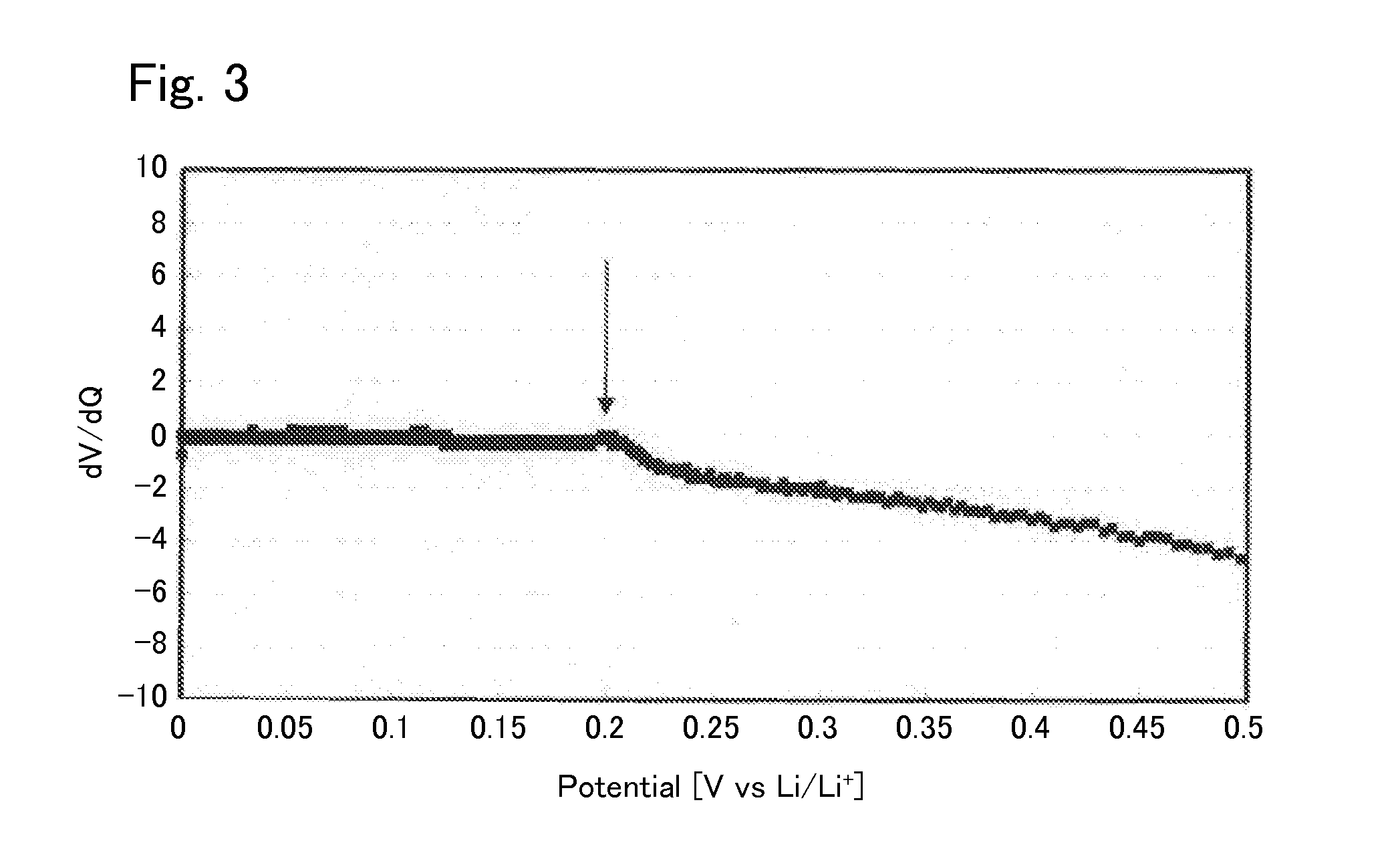
[0040]Under argon atmosphere, 0.425560 g of Li2S (manufactured by Nippon Chemical Industrial CO., LTD.), 0.3796162 g of P2S5 (manufactured by Aldrich), 0.125778 g of GeS2 (manufactured by KOJUNDO CHEMICAL LABORATORY CO., LTD), and 0.069045 g of Al2S3 (manufactured by KOJUNDO CHEMICAL LABORATORY CO., LTD) were weighed and put in a zirconia pot (capacity: 45 ml) together with 10 of zirconia balls each having a diameter of 10 mm. The pot was sealed under argon atmosphere. After that, the pot was attached to a planetary ball mill machine (manufactured by Fritsch, P-7) and rotated at a speed of 370 rotations per minute for 40 hours, whereby the contents of the pot were mixed. Then, the obtained mixed powder was put in a quartz tube. The pressure inside the quartz tube was reduced to 30 Pa, thereafter the quarts tube was sealed. After that, the sealed quarts tube was heated at 550° C. for 8 hours, whereby the sulfide solid electrolyte according to Example 1 was syn...
example 2
[0046]A sulfide solid electrolyte according to Example 2 was synthesized in the same manner as in Example 1, except that the starting materials in synthesizing the electrolyte were 0.397341 g of Li2S (manufactured by Nippon Chemical Industrial CO., LTD.), 0.369102 g of P2S5 (manufactured by Aldrich), 0.220129 g of GeS2 (manufactured by KOJUNDO CHEMICAL LABORATORY CO., LTD), and 0.013426 g of Al2S3 (manufactured by KOJUNDO CHEMICAL LABORATORY CO., LTD).
[0047]The composition of the synthesized sulfide solid electrolyte according to Example 2 was Li3.385Al0.035Ge0.315P0.65S4. In the sulfide solid electrolyte according to Example 2, M0≈0.05385 was satisfied.
[0048]In addition, regarding the sulfide solid electrolyte according to Example 2, an X-ray diffraction measurement was carried out in the same manner as in Example 1. The result is shown in FIG. 4. Comparing FIG. 4 and FIG. 1, it was found that they had peaks at the same positions. Therefore, the structure of the sulfide solid elect...
example 3
[0050]A sulfide solid electrolyte according to Example 3 was synthesized in the same manner as in Example 1, except that the starting materials in synthesizing the electrolyte were 0.403205 g of Li2S (manufactured by Nippon Chemical Industrial CO., LTD.), 0.414400 g of P2S5 (manufactured by Aldrich), 0.129300 g of SnS2 (manufactured by KOJUNDO CHEMICAL LABORATORY CO., LTD), and 0.053094 g of Al2S3 (manufactured by KOJUNDO CHEMICAL LABORATORY CO., LTD).
[0051]The composition of the synthesized sulfide solid electrolyte according to Example 3 was Li3.4125Al0.1375Sn0.1375P0.725S4. In the sulfide solid electrolyte according to Example 3, M0≈0.18966 was satisfied.
[0052]In addition, regarding the sulfide solid electrolyte according to Example 3, an X-ray diffraction measurement was carried out in the same manner as in Example 1. The result is shown in FIG. 7. Comparing FIG. 7 and FIG. 1, it was found that they had peaks at the same positions. Therefore, the structure of the sulfide solid e...
PUM
| Property | Measurement | Unit |
|---|---|---|
| 2θ | aaaaa | aaaaa |
| reduction resistant property | aaaaa | aaaaa |
| reduction decomposition potential | aaaaa | aaaaa |
Abstract
Description
Claims
Application Information
 - R&D
- Intellectual Property
- Life Sciences
- Materials
- Tech Scout
- Unparalleled Data Quality
- Higher Quality Content
- 60% Fewer Hallucinations
Browse by: Latest US Patents, China's latest patents, Technical Efficacy Thesaurus, Application Domain, Technology Topic, Popular Technical Reports.
© 2025 PatSnap. All rights reserved.Legal|Privacy policy|Modern Slavery Act Transparency Statement|Sitemap|About US| Contact US: help@patsnap.com


