
Pixel structure and method of fabricating the same

a technology of pixel structure and transistor, applied in the direction of thermoelectric device junction materials, semiconductor devices, electrical apparatus, etc., can solve the problems of poor uniformity, high process complexity, and inability to meet the requirements of foreseeable high-performance display devices, and achieve the effect of improving the device characteristic of the thin film transistor devi

Active Publication Date: 2015-07-30
AU OPTRONICS CORP
View PDF8 Cites 21 Cited by
  • Summary
  • Abstract
  • Description
  • Claims
  • Application Information

AI Technical Summary

Benefits of technology

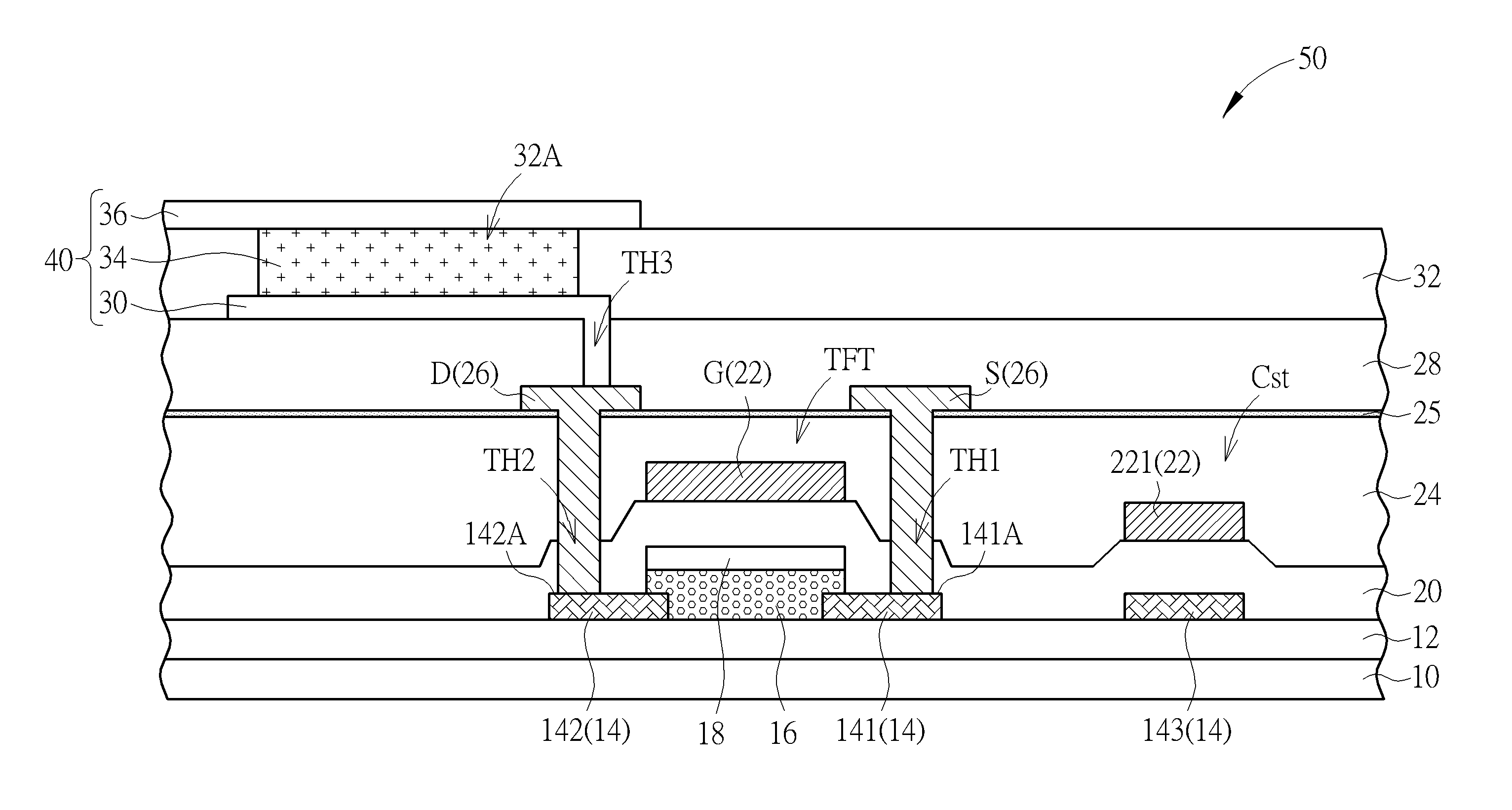
The present disclosure provides a pixel structure and method of fabricating it to improve the device characteristic of thin film transistor device of the pixel structure. The pixel structure uses connection electrodes to connect the source electrode / drain electrode and the oxide semiconductor channel layer, which avoids the defect of the direct contact between the source electrode / drain electrode and the oxide semiconductor channel layer. This improves the device characteristic of the thin film transistor device.

Problems solved by technology

The amorphous silicon thin film transistor device is not able to satisfy requirements of foreseeable high performance display devices because of its low electron mobility.
However, because of process issues such as high process complexity and poor uniformity, which is mainly generated by crystallization processes applied to large size substrates, the poly silicon thin film transistor device is mainly applied in small size display device.
In the oxide semiconductor thin film transistor device, the high contact resistance between the source electrode / drain electrode and the oxide semiconductor layer would reduce the efficiency regardless of its high electron mobility.

Method used


Image

  • Pixel structure and method of fabricating the same
  • Pixel structure and method of fabricating the same
  • Pixel structure and method of fabricating the same

Examples


Embodiment Construction

[0018]To provide a better understanding of the present disclosure, preferred embodiments will be made in detail. The preferred embodiments of the present disclosure are illustrated in the accompanying drawings with numbered elements.

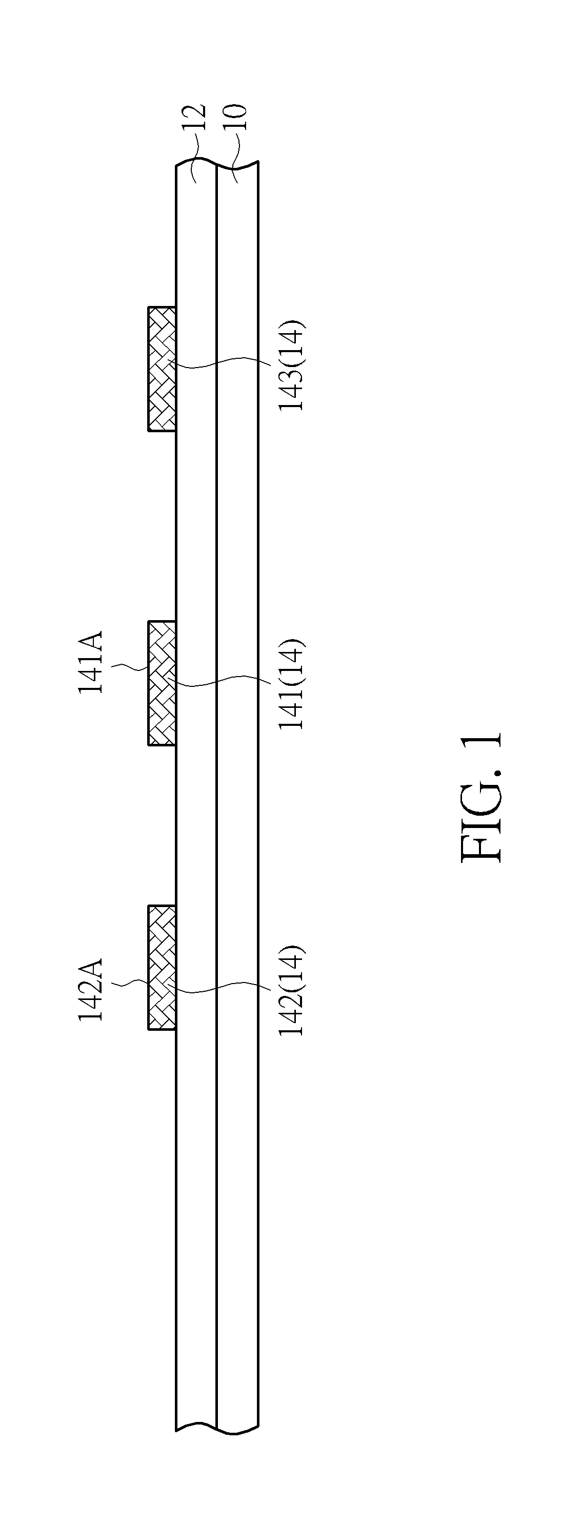
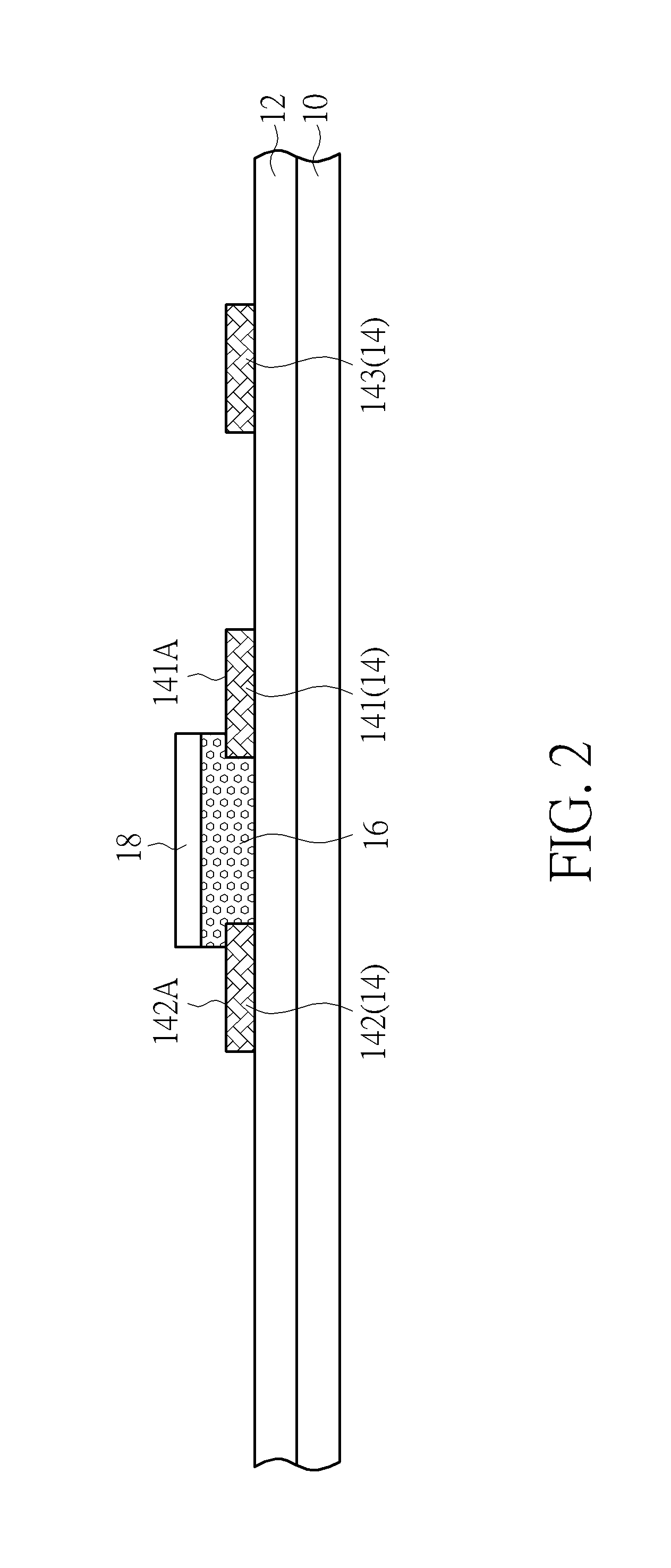
[0019]Refer to FIGS. 1-6. FIGS. 1-6 are schematic diagrams illustrating a method of fabricating pixel structure according to a first embodiment of the present disclosure. As shown in FIG. 1, a substrate 10 is provided. The substrate 10 may be a transparent substrate, which may be a rigid substrate or a flexible substrate e.g. a glass substrate, a quartz substrate or a plastic substrate. Then, a buffer layer 12 may be optionally formed on the substrate 10. The buffer layer 12 is insulating, and the material of the buffer layer 12 may be inorganic insulating material e.g. silicon oxide, silicon nitride or silicon oxynitride, or organic insulating material. Also, the buffer layer 12 may be a single-layered structure or a multi-layered structure. Subsequentl...


PUM


Abstract

A pixel structure includes a thin film transistor device. The thin film transistor device includes a first connection electrode, a second connection electrode, an oxide semiconductor channel layer, a gate insulation layer, a gate electrode, a dielectric layer, a source electrode and a drain electrode. The oxide semiconductor channel layer at least partially covers a top surface of the first connection electrode and a top surface of the second connection electrode. The gate electrode is disposed on the gate insulation layer. The dielectric layer is disposed on the gate electrode and the gate insulation layer. The gate insulation layer and the dielectric layer have a first contact hole at least partially exposing the top surface of the first connection electrode and a second contact hole at least partially exposing the top surface of the second connection electrode. The source electrode is electrically connected to the first connection electrode via the first contact hole, and the drain electrode is electrically connected to the second connection electrode via the second contact hole.

Description

BACKGROUND OF THE DISCLOSURE[0001]1. Field of the Disclosure[0002]The present disclosure relates to a pixel structure and method of fabricating the same, and more particularly, to a pixel structure in which source electrode / drain electrode and oxide semiconductor channel layer are electrically connected through connection electrodes, and method of fabricating the same.[0003]2. Description of the Related Art[0004]Thin film transistor (TFT) device is a kind of semiconductor devices commonly used in various types of display devices, such as liquid crystal display (LCD) devices, organic light-emitting diode (OLED) display devices and electronic paper (E-paper). The electron mobility of thin film transistor device is crucial to its switching rate, and thus is critical to display quality.[0005]According to different semiconductor materials applied in the thin film transistor device, the thin film transistor devices in current display industries may include amorphous silicon thin film tran...

Claims


Application Information

Patent Timeline
Patent Type & Authority Applications(United States)
IPC IPC(8): H01L27/12H01L51/56H01L29/66H01L27/32
CPCH01L27/1225H01L27/3244H01L2227/323H01L51/56H01L29/66969H01L27/1255H01L27/1214H01L27/1259H01L29/78639H10K59/1213H10K59/1216
Inventor CHOU, CHENG-WEI
Owner AU OPTRONICS CORP
Learn More