Power module package and method of manufacturing the same

a technology of power module and power module package, which is applied in the direction of electrical equipment, semiconductor devices, semiconductor/solid-state device details, etc., can solve the problems of limited thermal properties, limited usable thickness of ceramic substrates, and inability to meet the thermal properties of power modules, so as to increase the efficiency and reliability of power modules, improve thermal properties

Active Publication Date: 2015-07-30
SAMSUNG ELECTRO MECHANICS CO LTD
View PDF1 Cites 7 Cited by
  • Summary
  • Abstract
  • Description
  • Claims
  • Application Information

AI Technical Summary

Benefits of technology

The invention improves the heat transfer in a power module to make it more efficient and reliable. It also provides a package that can easily improve the heat transfer.

Problems solved by technology

Therefore, since heat radiation of the power device is mainly performed by the lead frame and an epoxy molding compound (EMC) having low thermal conductivity, thermal property required in the power module may not be satisfied.
However, the structure has a problem in that all the devices are mounted on the lead frame and thus thermal property is limited and the thermal property totally relies on thermal property of the ceramic substrate.
That is, the ceramic substrate has a limitation of a usable thickness due to material properties.
However, the DBC substrate is generally more expensive than a thermal substrate and is thus expensive in proportion to improvement in the thermal property.

Method used


Image

  • Power module package and method of manufacturing the same
  • Power module package and method of manufacturing the same
  • Power module package and method of manufacturing the same

Examples


first preferred embodiment

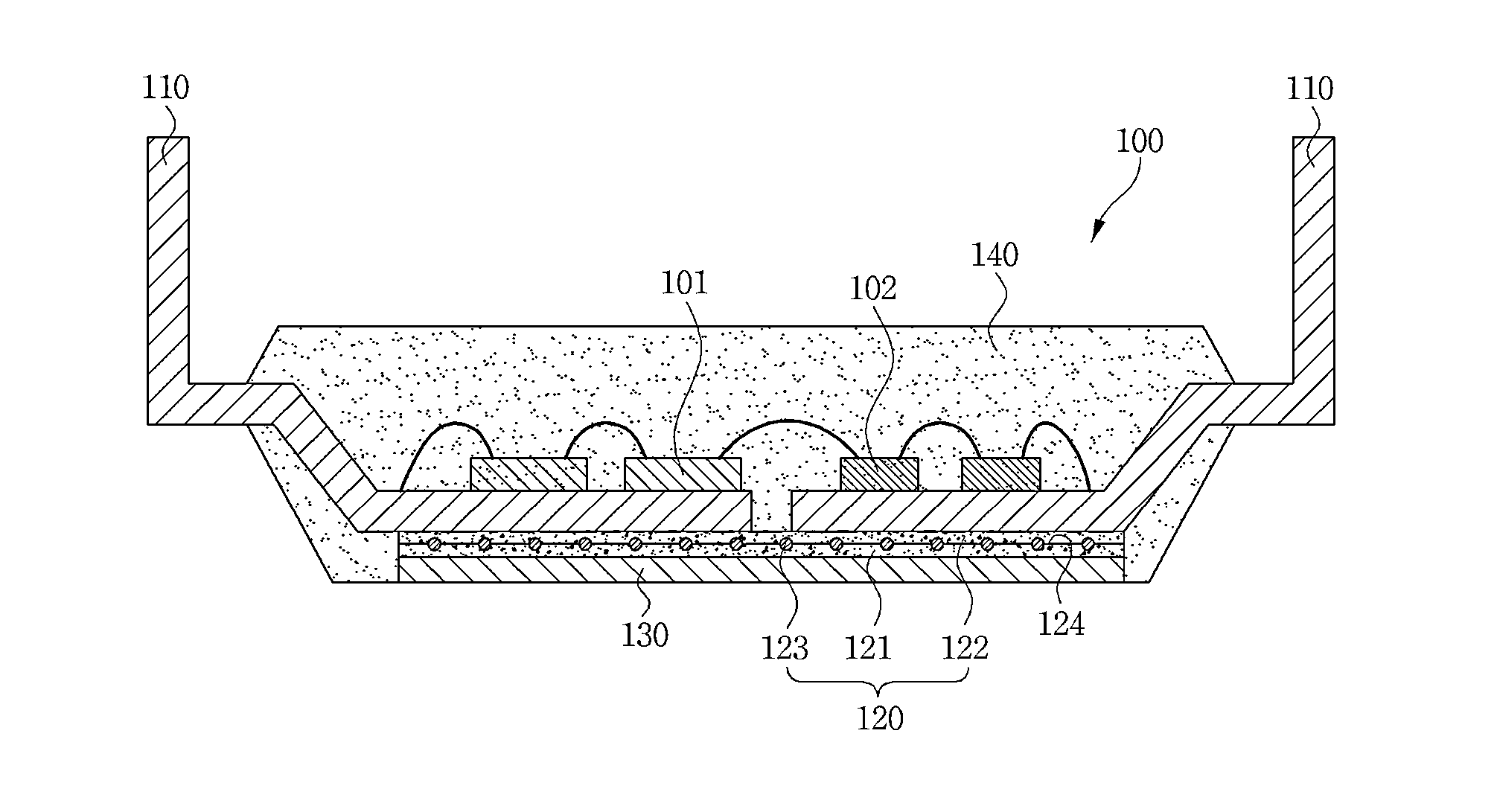
[0039]As illustrated in FIGS. 1 to 3, a power module package 100 according to a preferred embodiment of the present invention may include a lead frame 110 on which a power device 101 and a control IC 102 controlling the power device 101 are mounted, a thermal sheet 120 which is bonded to one surface of the lead frame 110, a metal layer 130 which is bonded to the thermal sheet 120, and a molding part 140 which molds these devices.

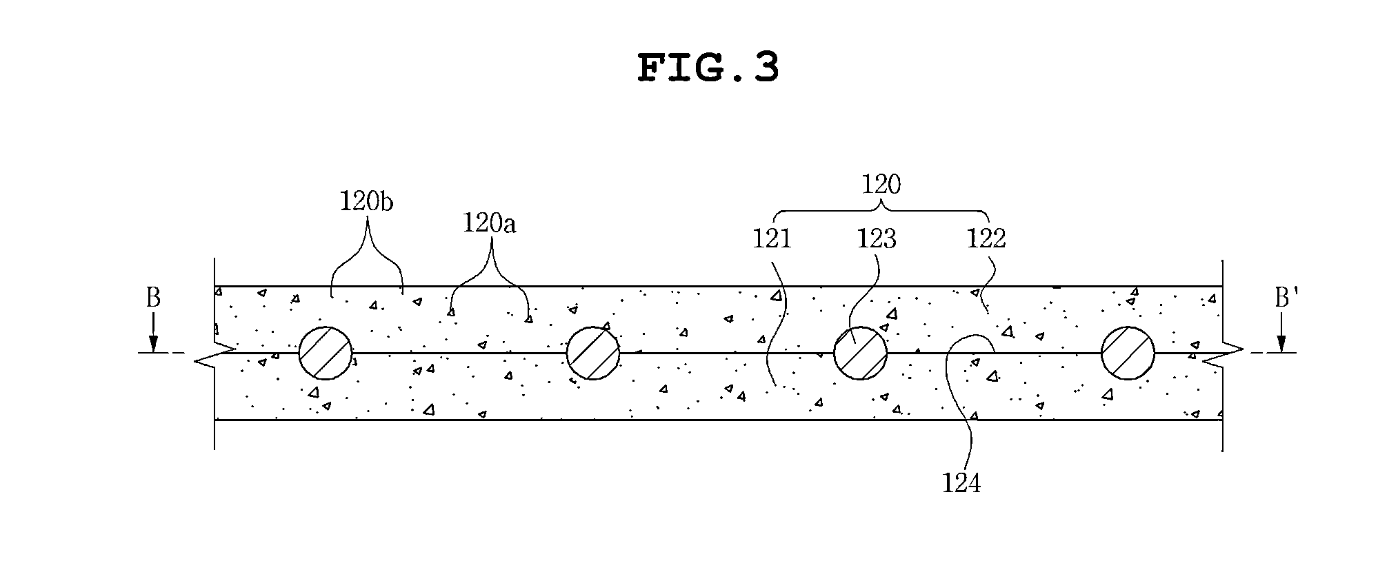
[0040]The thermal sheet 120 is made of an organic material including prepreg, epoxy, polyimide, and liquid crystal polymer and includes first and second resin layers 121 and 122 including a thermal conductive inorganic filler 120a and added with a mixture 120b improving a bonding strength to have high thermal conductivity and adhesion and a thermal spreader 123 made of a metal material which is disposed at bonded interface 124 formed between the first and second resin layers 121 and 122.

[0041]Here, the inorganic filler 120a may be selected from a group consi...

second preferred embodiment

[0051]As illustrated in FIGS. 6 to 11, the method of manufacturing a power module package according to the embodiment of the present invention largely includes preparing the thermal sheet 120 and manufacturing the power module package 100 using the thermal sheet 120.

[0052]The thermal sheet 120 includes the first and second resin layers 121 and 122 which are made of the organic material, etc., including prepreg, epoxy, polyimide, liquid crystal polymer, and the like.

[0053]Here, the first and second resin layers 121 and 122 include the thermal conductive inorganic filler of 80% or more which may be selected from a group consisting of, for example, aluminum oxide (Al2O3), aluminum nitride (MN), silicon nitride (SiN), silicon dioxide (SiO2), silicon carbide (SiC), or a combination thereof and are added with the mixture 120b of phenyl glycidyl ether (PGE) and alkyl (C12 to C 14), glycidyl ether (Alkyl (C12 to C14) glycidyl ether) which are mixed at a mixing ratio of 2:1 to improve the bo...


PUM


Abstract

Disclosed herein are a power module package and a method of manufacturing the same. According to a preferred embodiment of the present invention, the power module package includes: a lead frame on which a power device and a control IC electrically connected to the power device and controlling the power device are mounted; and a thermal sheet bonded to one surface of the lead frame, wherein the thermal sheet includes first and second resin layers which include a thermal conductive inorganic filler and are added with a mixture of phenyl glycidyl ether (PGE) and alkyl glycidyl ether (Alkyl (C12 to C14) glycidyl ether), and a thermal spreader of a metal material disposed at a bonded interface which is formed between the first and second resin layers. Therefore, it is possible to easily improve a thermal property of the power module package by a thermal spreading effect due to the thermal spreader.

Description

CROSS REFERENCE TO RELATED APPLICATION[0001]This application claims the benefit of Korean Patent Application No. 10-2014-0010456, filed on Jan. 28, 2014, entitled “Power Module Package And Method Of Manufacturing The Same” which is hereby incorporated by reference in its entirety into this application.BACKGROUND OF THE INVENTION[0002]1. Technical Field[0003]The present invention relates to a power module package and a method of manufacturing the same.[0004]2. Description of the Related Art[0005]Generally, a power module is an electronic component which is mounted on a lead frame and has adopted a structure in which a power device and a control IC are bonded to each other and then molded. Therefore, since heat radiation of the power device is mainly performed by the lead frame and an epoxy molding compound (EMC) having low thermal conductivity, thermal property required in the power module may not be satisfied.[0006]Meanwhile, according to a power module package published in Patent D...

Claims


Application Information

Patent Timeline
Patent Type & Authority Applications(United States)
IPC IPC(8): H01L25/16H01L25/00H01L21/56H01L23/00H01L23/31H01L23/495H01L23/373
CPCH01L25/165H01L23/49575H01L23/49568H01L25/50H01L23/3735H01L2924/1203H01L23/3107H01L21/565H01L2924/14H01L2924/13091H01L2924/13055H01L24/85H01L23/3737H01L23/4334H01L23/49551H01L24/48H01L2224/48091H01L2224/48137H01L2224/48247H01L2924/181H01L2224/85H01L2224/45139H01L2224/45144H01L2224/45124H01L2224/45147H01L2224/4516H01L2224/45166H01L24/45H01L2924/00014H01L2924/00012
Inventor KIM, KWANG SOOCHAE, JOON SEOKKWAK, YOUNG HOON
Owner SAMSUNG ELECTRO MECHANICS CO LTD
Why Eureka
Try Eureka