
Integration of plasma and hydrogen process with combined cycle power plant, simple cycle power plant and steam reformers

a plasma and hydrogen technology, applied in the direction of machines/engines, mechanical equipment, separation processes, etc., can solve the problems of increasing raw material costs and energy resources, which are a substantial part of the cost of most if not all manufacturing processes, and achieve the effect of reducing coal consumption and reducing net air emissions

Inactive Publication Date: 2015-07-30
MONOLITH MATERIALS
View PDF9 Cites 30 Cited by
  • Summary
  • Abstract
  • Description
  • Claims
  • Application Information

AI Technical Summary

Benefits of technology

The patent describes methods for generating and recapturing electricity from power plants using natural gas and hydrogen. These methods involve converting natural gas to hydrogen and then using the hydrogen in a combined cycle power plant or a simple cycle power plant to produce electricity. The electricity is then either recaptured and flowed back into the hydrogen producing plant or released into the power grid, resulting in a reduction of air emissions. Additionally, the patent also describes methods for reducing the consumption of fossil fuels and associated air emissions at steam power plants. The technical effects of the patent include the generation and recapture of electricity, as well as the reduction of air emissions from power plants.

Problems solved by technology

This can take the form of raw material costs, energy costs, or simple improvement in process efficiencies, among other things.
In general, raw material costs and energy resources, which are a substantial part of the cost of most if not all manufacturing processes, tend to actually increase over time, because of scale up and increased volumes, if for no other reasons.

Method used


Image

  • Integration of plasma and hydrogen process with combined cycle power plant, simple cycle power plant and steam reformers
  • Integration of plasma and hydrogen process with combined cycle power plant, simple cycle power plant and steam reformers
  • Integration of plasma and hydrogen process with combined cycle power plant, simple cycle power plant and steam reformers

Examples


example 1

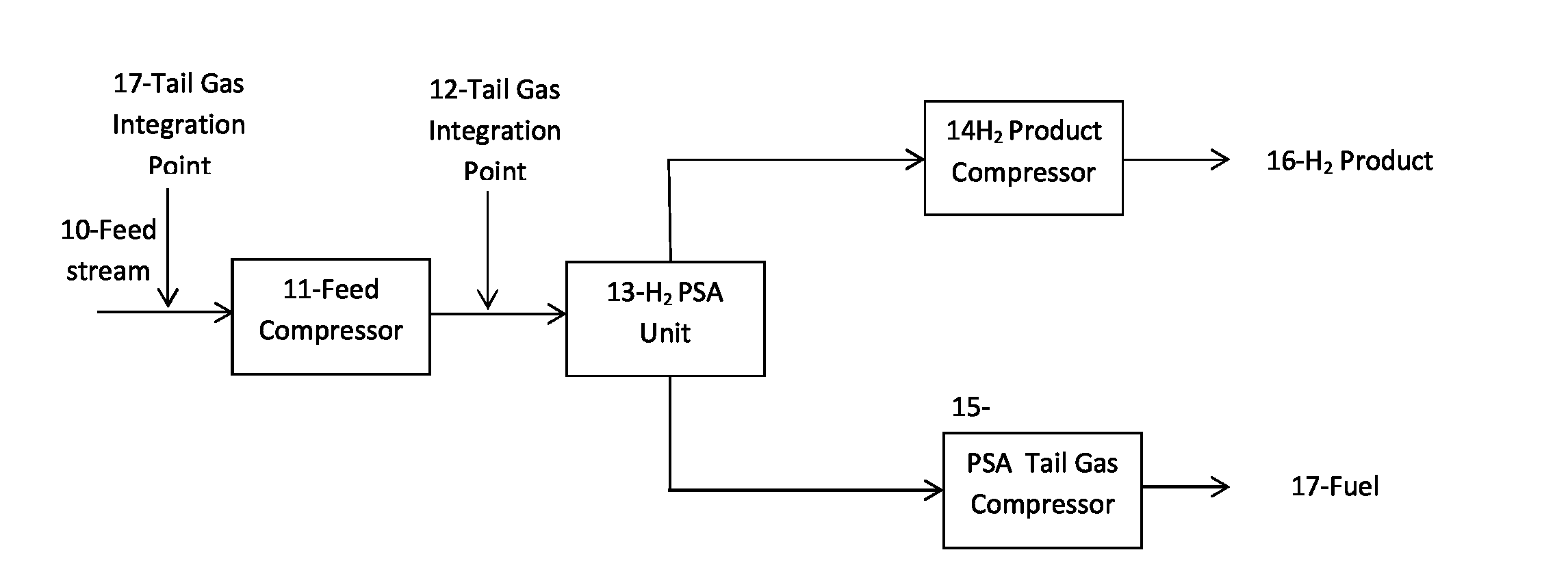
[0032]As shown schematically in FIG. 1, a feed stream (10) of 70.000 million standard cubic feet per day (MMSCFD), of hydrogen at 97.49% purity, 10 pounds per square inch gauge (psig), 100° F., 973.1 million British thermal units (MMBTU) higher heating value (HHV / hour), and 824.4 MMBTU lower heating value (LHV / hour) was flowed into a feed compressor (11) at 2×7000 NHP (Nominal Horse Power Flow rate=70 MMSCFD). At this point the tail gas (12) from a carbon black production plant is added to the compressed stream prior to it entering into the PSA unit (13). It should also be noted that it is not required that there be a feed stream and an additional tail gas stream. The feed stream can be just the tail gas from a plasma process stream and added at the front end of the system (17). The tail gas properties are shown in the Table below.

TABLEFlowrateMMSCFD70Pressurepsig10Temperature° F.100Molecular Weightgrams / mole2.53HydrogenMol %:97.49%NitrogenMol %:0.20%Carbon MonoxideMol %:1.00%Methan...

example 2

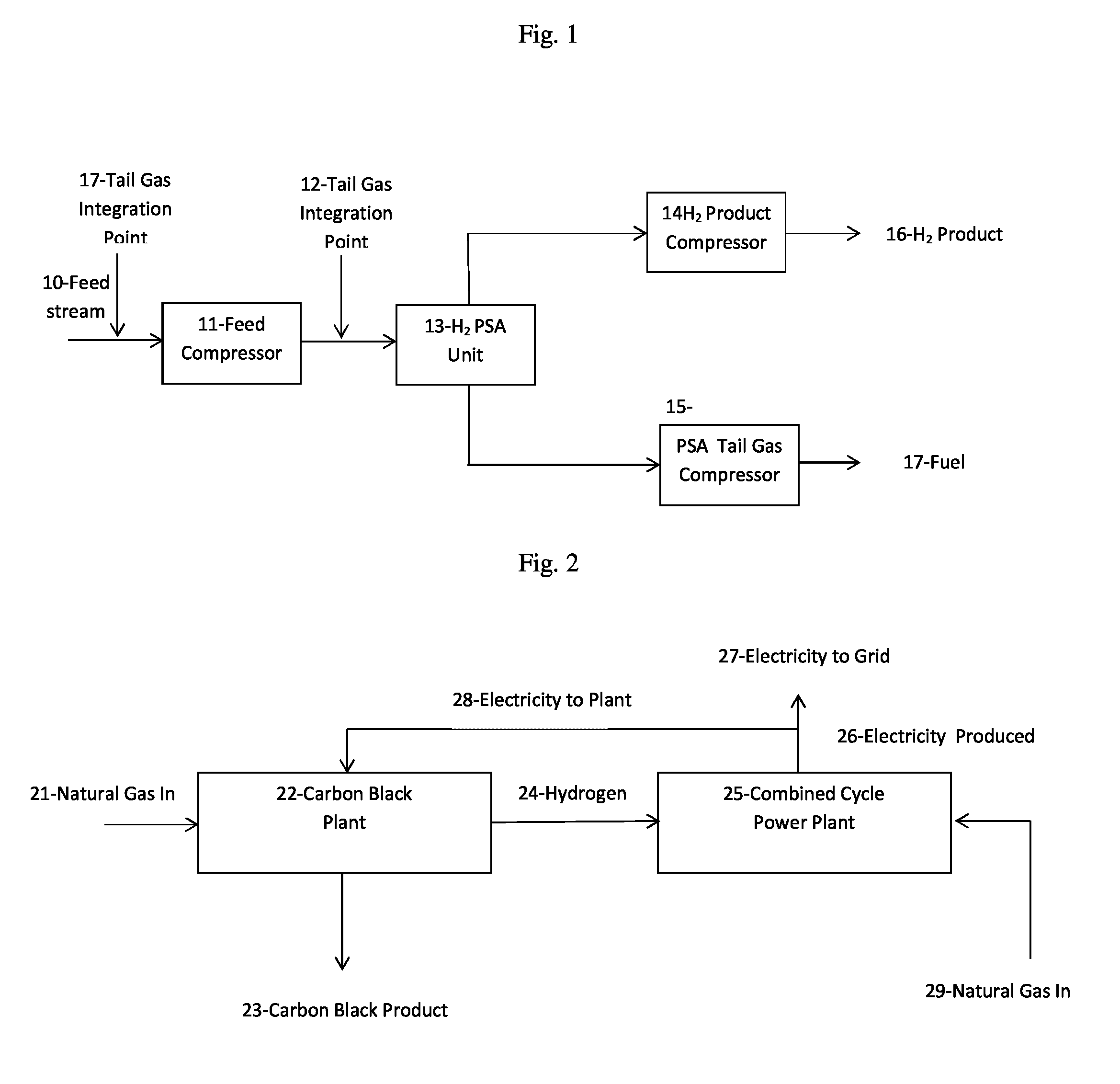
[0034]FIG. 2 shows schematically natural gas (21) with the following properties—1750.0 BTU / hour, 34.5 tons / hr.—going into the carbon black generating plant (22) with the following properties—electrical efficiency 7 megawatts per hour per ton (MW / hr / ton), feedstock efficiency 70 MMBTU / ton, carbon black production 200,000 tons / year and 25.00 tons / hour—generating carbon black (23) and hydrogen (24) with the following properties—1038 MMBTU / hour, and 9.5 tons per hour. The hydrogen is flowed into a combined cycle power plant (25) with the following properties—heat rate fuel 6500 BTU / kilowatt hour (KWh), heat rate steam 8500 BTU / KWh—producing 1157.6 megawatts (MW) of electricity, (26) 553 MW of which is flowed into a grid (27) and 175.0 MW (159.7 from hydrogen, 28.7 from steam, and 13.4 MW excess needed / produced) which is flowed back into the carbon black generating plant (22). Natural gas (29) with the following properties—6300 MMBTU / hour—is also flowed into the combined cycle power plan...

example 3

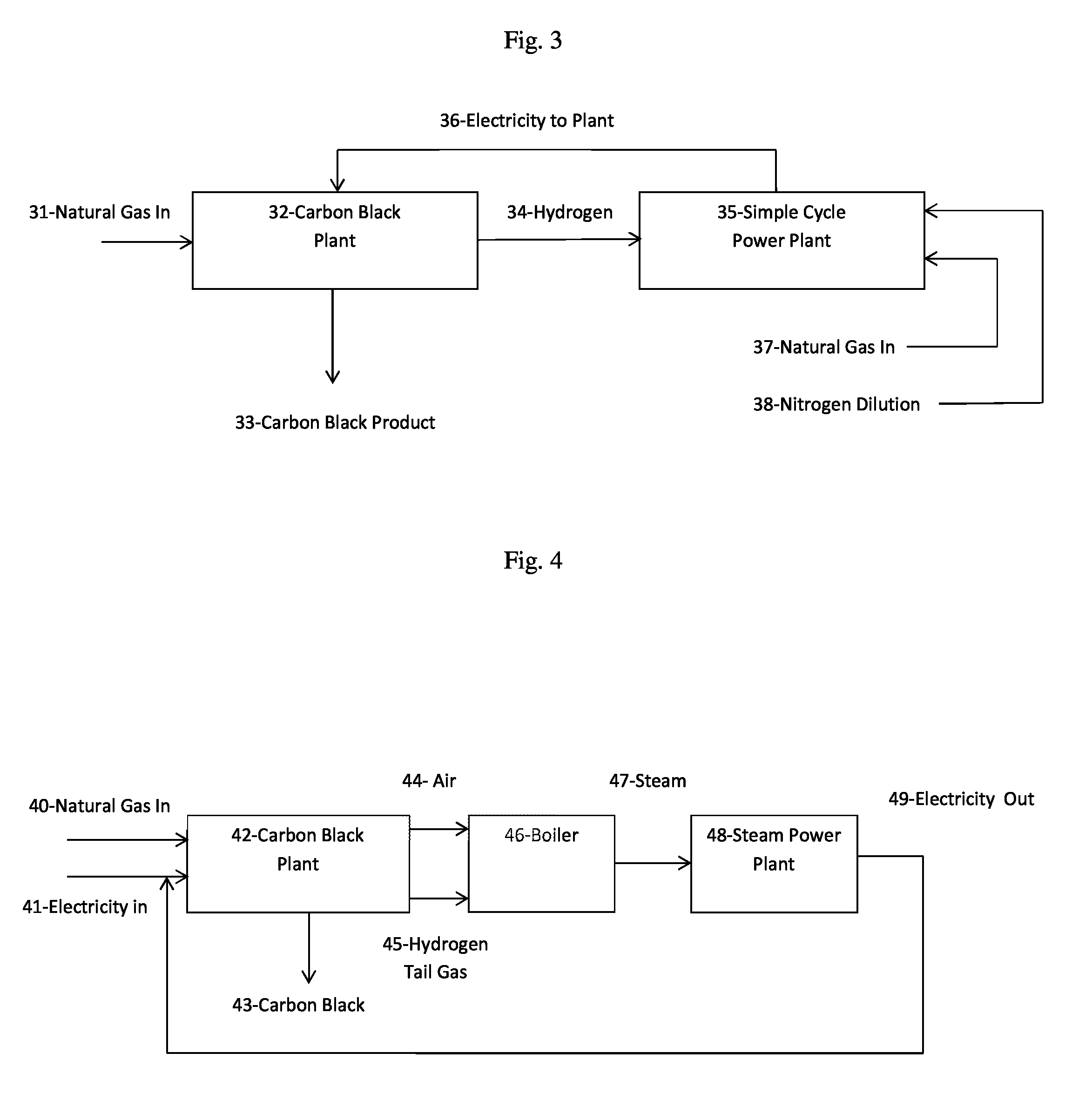
[0035]As shown schematically in FIG. 3, natural gas (31) with the following properties—1,750.0 MMBTU / hour, 34.5 tons per hour (tons / hr)—going into a carbon black generating plant (32) with the following properties—electrical efficiency 7 MW / hr / ton, feedstock efficiency 70 MMBTU / ton, carbon black production 200,000 tons / year and 25.00 tons / hour, with a carbon dioxide reduction of 322,787 tons per year, and a total feedstock efficiency of 87.5 MMBTU per ton—generating carbon black (33) and hydrogen (34) with the following properties—1050.0 MMBTU / hour, 9.5 tons / hr, 106,991 Nm3 / hr (normal meter, i.e., cubic meter of gas at normal conditions, i.e. 0° C., and 1 atmosphere of pressure). The hydrogen is flowed into a simple cycle power plant (35) with the following properties—heat rate fuel 8500 BTU / KWh—producing 175.0 MW of electricity (36) (123.5 from hydrogen, 51.5 from natural gas) which is flowed back into the carbon black generating plant (32). Natural gas (37) with the following prop...


PUM

PropertyMeasurementUnit
pressureaaaaaaaaaa
electrical efficiencyaaaaaaaaaa
electrical energyaaaaaaaaaa

Abstract

The integration of plasma processes with combined cycle power plant, simple cycle power plant, and steam reforming processes. A method of producing purified hydrogen gas and fuel is described including compressing a feed stream of hydrogen, adding tail gas from a plasma process to the feed stream, passing the tail gas modified feed stream into a pressure swing adsorption system generating a purified hydrogen product and a pressure swing adsorption tail gas, separating and compressing the purified hydrogen product, and separating and compressing the pressure swing adsorption tail gas for use as fuel. A method of generating and recapturing electricity from a single or combined cycle power plant is also described including flowing natural gas into a plasma process and hydrogen generating plant, flowing the hydrogen produced into the power plant, flowing natural gas into the power plant, resulting in the production of electricity. The electricity is flowed back into the plasma process plant, and in the case of the combined cycle power plant the electricity is partially flowed into a power grid as well. A method of generating and recapturing electricity from a steam power plant is also described, including inputting electricity and natural gas into a plasma process air and hydrogen generating plant, flowing the air and hydrogen produced into a steam generating boiler, flowing the steam generated into a steam power plant, resulting in the production of electricity which is flowed back into the plasma process plant.

Description

CROSS-REFERENCE TO RELATED APPLICATIONS[0001]The present application claims the benefit under 35 U.S.C. §119(e) of U.S. Provisional Application No. 61 / 933,494 filed Jan. 30, 2014, the disclosure of which is expressly incorporated by reference herein in its entirety.TECHNICAL FIELD[0002]The field of art to which this invention generally pertains is methods and apparatus for making use of electrical energy to effect chemical changes.BACKGROUND[0003]No matter how unique the product or process, over time, all manufacturing processes look for ways to become more efficient and more effective. This can take the form of raw material costs, energy costs, or simple improvement in process efficiencies, among other things. In general, raw material costs and energy resources, which are a substantial part of the cost of most if not all manufacturing processes, tend to actually increase over time, because of scale up and increased volumes, if for no other reasons. For these, and other reasons, the...

Claims


Application Information

Patent Timeline
Patent Type & Authority Applications(United States)
IPC IPC(8): F01D15/10B01D53/047F02C6/00C01B3/56
CPCF01D15/10C01B3/56B01D2257/108F02C6/003C01B2203/042B01D53/047C01B3/24C01B2203/0266C01B2203/043C01B2203/0861C01B2203/1241B01D2256/16B01D2257/102B01D2257/408B01D2257/502B01D2257/7022B01D2257/7025Y02C20/20Y02P20/156F02C3/22F01K23/10C09C1/485Y02E20/16
Inventor JOHNSON, PETER L.HANSON, ROBERT J.TAYLOR, ROSCOE W.
Owner MONOLITH MATERIALS
Learn More