
Graphite composite material

Inactive Publication Date: 2015-07-09
KANEKA CORP
View PDF0 Cites 6 Cited by
  • Summary
  • Abstract
  • Description
  • Claims
  • Application Information

AI Technical Summary

Benefits of technology

The present invention provides a way to make a material that has a layer of graphite and a layer of resin. The invention stops the resin layer from splitting from the graphite film.

Problems solved by technology

Graphite film has high heat dissipation properties due to its high heat conductivity, but tends to be poor in adhesion to resin or other materials due to its low surface activity.
However, when a resin layer is directly formed on the surface of a graphite film, the resulting graphite composite material has low mechanical strength due to low interlaminar strength between the graphite film and the resin layer.

Method used


Image

  • Graphite composite material
  • Graphite composite material
  • Graphite composite material

Examples


example 1

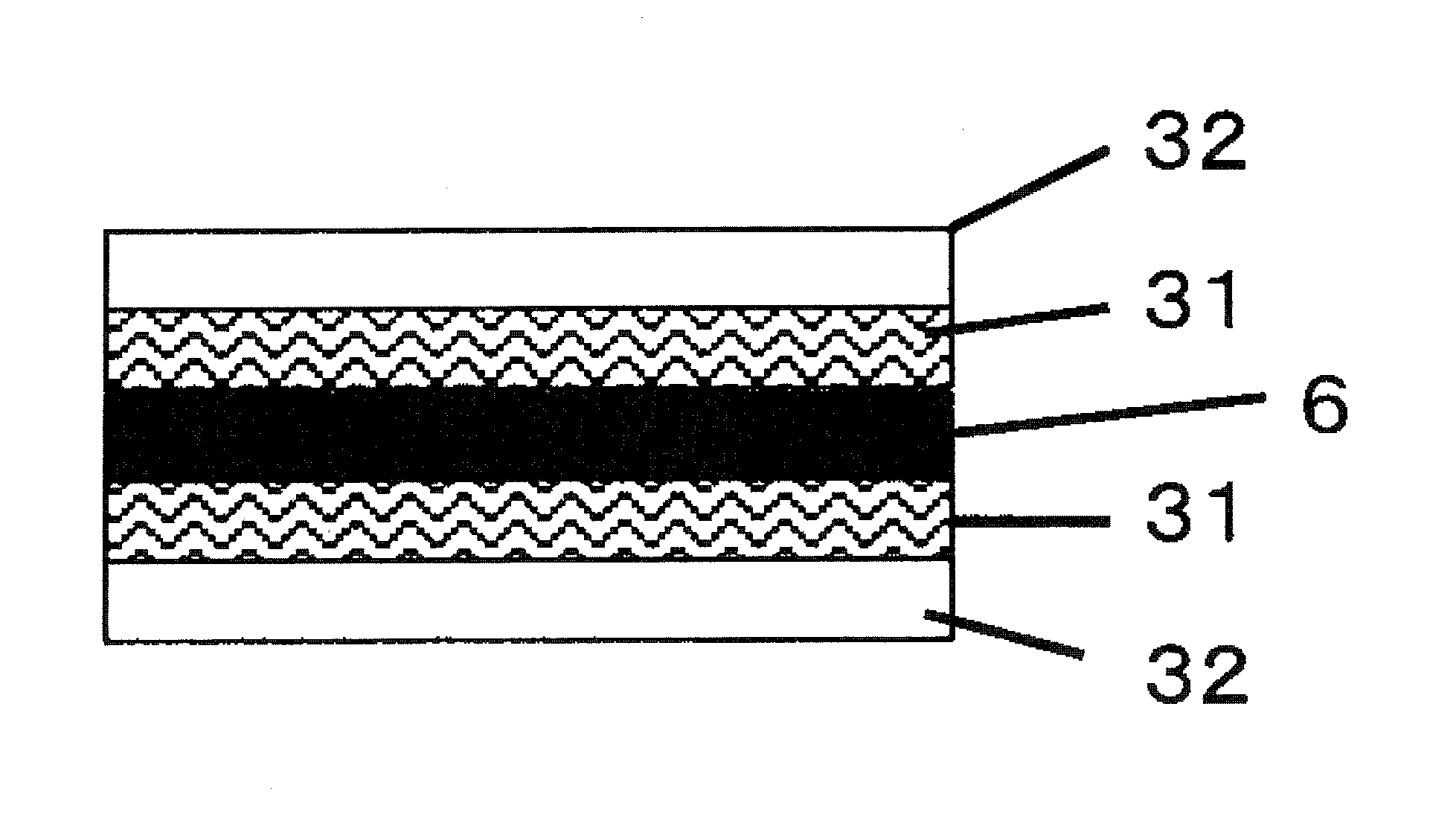
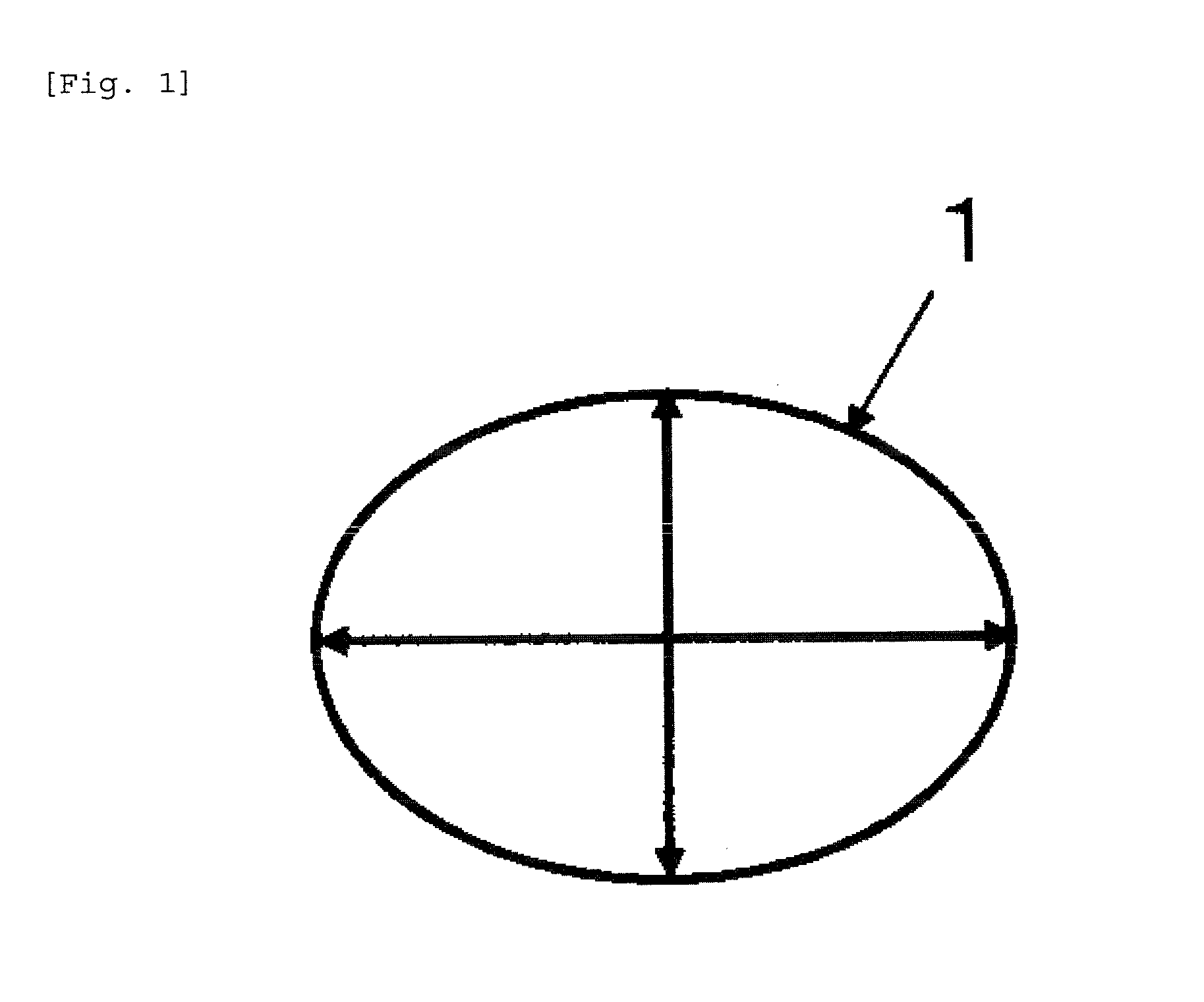
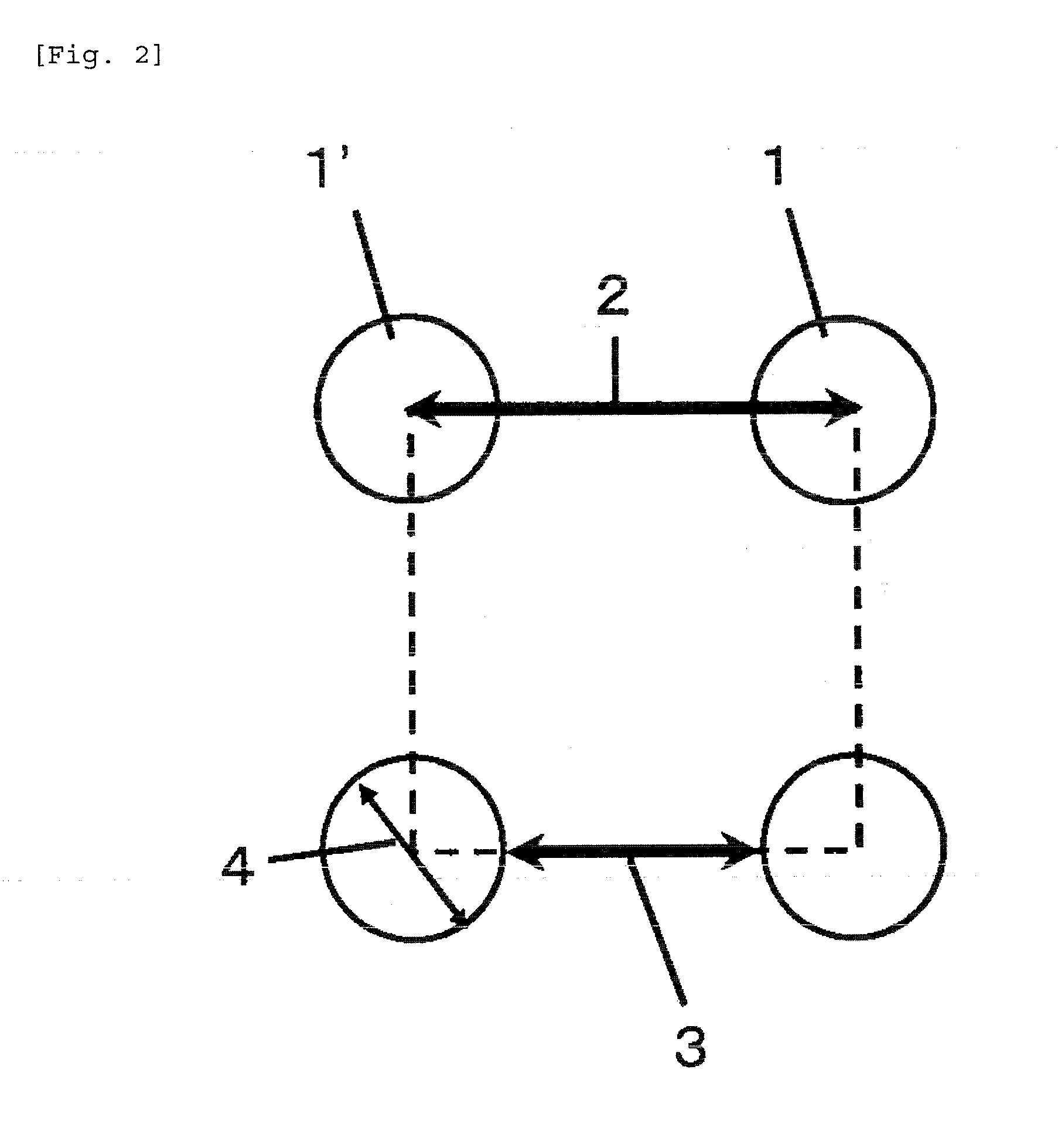
[0046]Through holes were formed by cutting out circles in the graphite film (thickness: 40 μm) with Laser Marker MD-T1010 manufactured by KEYENCE CORPORATION at a laser wavelength of 532 nm, a laser power of 80%, a frequency of 50 kHz, and a rate of 50 mm / min. Then, graphite powder created by laser processing was removed in an ultrasonic bath. The through holes had a diameter of 0.10 mm, and the pitch between the through holes was 0.70 mm (Number of through holes: 204 per cm2, Distance between outer diameters of through holes: 0.60 mm, Rate of hole area: 1.6%). Then, as shown in FIG. 4, glass-epoxy prepregs 31 (R1661 (100 μm) manufactured by Panasonic Corporation, corresponding to the resin layers in the present invention) were stacked on both surfaces of the graphite film 6, and rolled copper foils 32 (35 μm) were further stacked on the outside of the glass-epoxy prepregs 31 to obtain a layered structure. Then, this layered structure was hot-pressed to produce a graphite composite ...

example 2

[0047]A graphite composite material was produced in the same manner as in Example 1 except that the through holes formed in the graphite film had a diameter of 0.15 mm, and the pitch between the through holes was 0.70 mm (Number of through holes: 204 per cm2, Distance between outer diameters of through holes: 0.55 mm, Rate of hole area: 3.6%). The results are shown in Table 1.

example 3

[0048]A graphite composite material was produced in the same manner as in Example 1 except that the through holes formed in the graphite film had a diameter of 0.20 mm, and the pitch between the through holes was 0.70 mm (Number of through holes: 204 per cm2, Distance between outer diameters of through holes: 0.50 mm, Rate of hole area: 6.4%). The results are shown in Table 1.


PUM

PropertyMeasurementUnit
Diameteraaaaaaaaaa
Diameteraaaaaaaaaa
Fracture energyaaaaaaaaaa

Abstract

Disclosed herein is a graphite composite material including a graphite film and a resin layer, wherein peeling-off of the resin layer from the graphite film is suppressed. The graphite composite material includes: a graphite film; and a resin layer formed on at least one surface of the graphite film, wherein the graphite film has through holes, wherein a number of the through is 100 to 1000 per cm2, and the through holes have a diameter of 0.10 mm or more but 1.00 mm or less, and wherein part of the resin layer is formed also in the through holes.

Description

TECHNICAL FIELD[0001]The present invention relates to a graphite composite material including a resin layer and a graphite film layer.BACKGROUND ART[0002]Graphite film has high heat dissipation properties due to its high heat conductivity, but tends to be poor in adhesion to resin or other materials due to its low surface activity. For example, when used as a heat dissipation material for circuit boards (Patent Document 1), a graphite film needs to be combined with a resin. However, when a resin layer is directly formed on the surface of a graphite film, the resulting graphite composite material has low mechanical strength due to low interlaminar strength between the graphite film and the resin layer. Particularly, in the case of a structure, such as a circuit board having a metal layer, in which volatile matter in materials is less likely to be discharged to the outside of a system, there is a case where, due to the low interlaminar strength between the graphite film and the resin ...

Claims


Application Information

Patent Timeline
IPC IPC(8): B32B7/04B32B9/04B32B3/26B32B9/00C01B31/04H05K1/02
CPCB32B7/04C01B31/0423H05K1/0203B32B3/266B32B9/007B32B2457/08B32B2250/40B32B2250/03B32B2307/302B32B2313/04B32B9/045H01L23/373H01L23/3735H05K1/0207H05K3/022H05K2201/0323H05K2201/10106H05K2201/2072H05K3/44H01L2924/0002B32B9/047B32B15/20B32B17/04C01B32/225Y10T428/24347H01L2924/00
Inventor KUTSUMIZU, MAKOTONISHIKAWA, YASUSHIOHTA, YUSUKEKATAYAMA, SATOSHIINADA, TAKASHIKOBAYASHI, MOTOAKI
Owner KANEKA CORP
Learn More