Resonator element, resonator, oscillator, electronic apparatus, sensor, and mobile object

a technology of resonator and oscillator, which is applied in the direction of generator/motor, force measurement, instruments, etc., can solve the problems of loss of vibration balance of the vibrating arm after a frequency adjustment, increased vibration leakage, and difficulty in removing the weight layer with a high level of accuracy, and achieves excellent reliability

Inactive Publication Date: 2015-07-02
SEIKO EPSON CORP
View PDF3 Cites 10 Cited by
  • Summary
  • Abstract
  • Description
  • Claims
  • Application Information

AI Technical Summary

Benefits of technology

The invention provides a resonator element that can accurately adjust the resonance frequency of a vibrating arm, which is important for the performance of electronic devices and sensors. The design reduces rigidity differences between different parts of the vibrating arm, which helps to prevent stress concentration and maintain impact resistance. Additionally, the design allows for an increase in the mass of certain parts, which helps to achieve stable vibration characteristics and improve the reliability of the mobile object.

Problems solved by technology

However, in the resonator element disclosed in JP-A-2012-044235, the weight layer is provided in the first weight portion of which the distal end side has a large width, and thus it is difficult to remove the weight layer with a high level of accuracy at the time of removing the weight layer using an ion beam.
This is because an area to be removed of the weight layer is large or variations occur in the amount of weight layer being removed due to a difficulty in managing the position accuracy of a metal mask, which is used at the time of irradiation with the ion beam, with a high level of accuracy and due to a difficulty in managing a distance between the metal mask and the resonator element with a high level of accuracy.
For this reason, a region irradiated with the ion beam extends along an extension direction of the vibrating arm and is shifted with respect to a center line of the vibrating arm which passes through the center of the length of the vibrating arm (width of the vibrating arm) in a direction perpendicular to the extension direction when seen in a plan view, and thus there is a concern that the balance of the vibration of the vibrating arm after a frequency adjustment may be lost and vibration leakage may increase.
In addition, since distortion is present in the tray and the metal mask, it is also difficult to manage a superposition distance at the time of superposing the tray and the metal mask on each other, with a high level of accuracy.
For this reason, the emitted ion beam is diffracted in the vicinity of an end of an opening of the metal mask, and thus the in-plane position and the amount of processing of the ion beam reaching the resonator element become unstable.
Accordingly, the amount of weight layer being removed using the ion beam varies due to the position, and thus there is a concern that the balance of the vibration of the vibrating arm after a frequency adjustment may be lost and vibration leakage may increase.
A film formed by a sputtering method often includes unnecessary gas involved during the film formation.
As a result, there is a problem in that the Q value is deteriorated due to an increase in air resistance at the time of bending vibration.

Method used


Image

  • Resonator element, resonator, oscillator, electronic apparatus, sensor, and mobile object
  • Resonator element, resonator, oscillator, electronic apparatus, sensor, and mobile object
  • Resonator element, resonator, oscillator, electronic apparatus, sensor, and mobile object

Examples


first embodiment

[0066]First, a resonator to which a resonator element according to the invention is applied (resonator according to the invention) will be described.

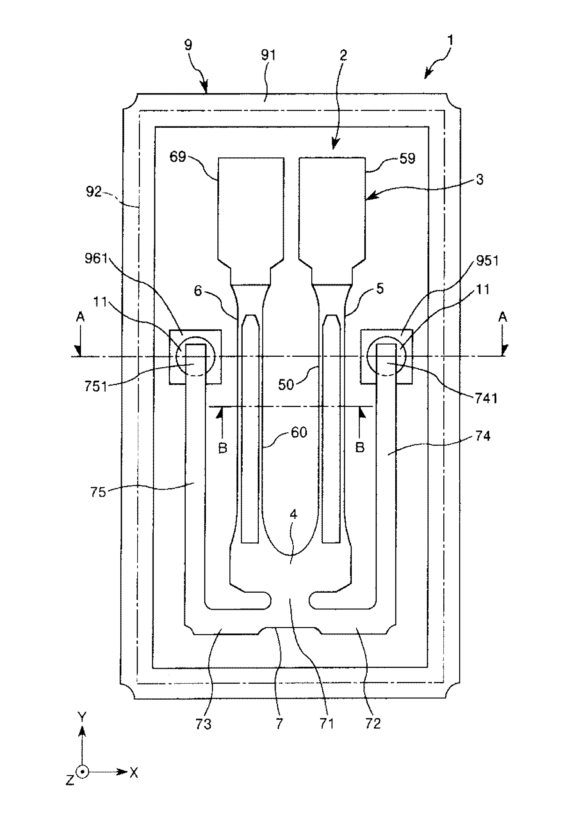
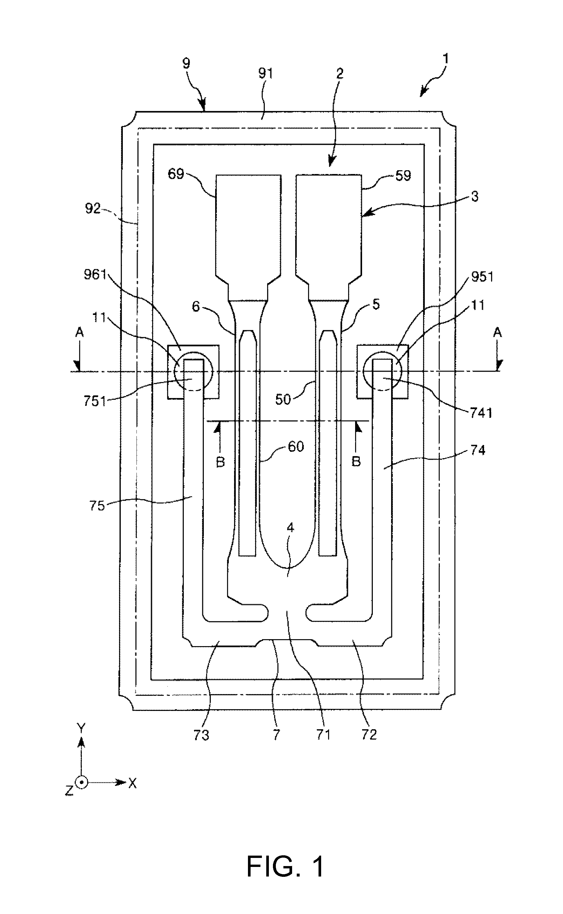
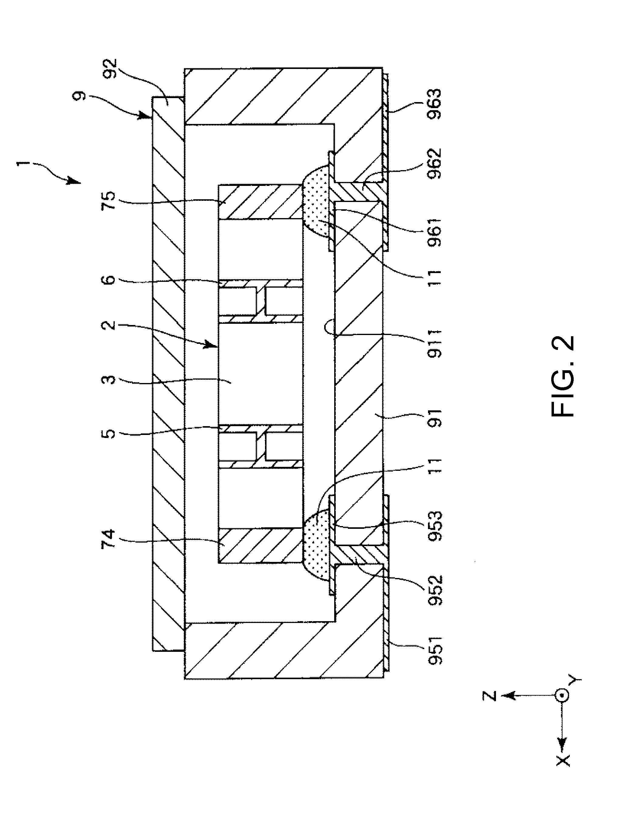
[0067]FIG. 1 is a plan view of a resonator according to a first embodiment of the invention. FIG. 2 is a cross-sectional view taken along line A-A in FIG. 1. FIG. 3 is a cross-sectional view (cross-sectional view taken along line B-B in FIG. 1) of a resonator element included in the resonator shown in FIG. 1. FIG. 4 is a diagram illustrating heat conduction at the time of the bending vibration of a vibrating arm. FIG. 5 is a graph showing a relationship between a Q value and f / fm.

[0068]Hereinafter, for convenience of description, as shown in FIG. 1, three axes orthogonal to each other are assumed to be an X-axis (electric axis), a Y-axis (mechanical axis), and a Z-axis (optical axis). In addition, a direction parallel to the X-axis (second direction) will be referred to as an “X-axis direction”, a direction parallel to the Y-axis (first...

second embodiment

[0145]Next, a second embodiment of the invention will be described.

[0146]FIG. 10 is a longitudinal sectional view showing a wide portion and a weight layer according to the second embodiment of the invention.

[0147]Hereinafter, the second embodiment will be described with a focus on differences from the above-described embodiment, and a description of the same matters will be omitted.

[0148]The second embodiment is substantially the same as the first embodiment except that the configuration of a weight layer is different. In FIG. 10, the same components as those in the above-described embodiment will be denoted by the same reference numerals.

[0149]In a vibrating arm 5A shown in FIG. 10, a weight layer (third weight portion) is provided on the surface side opposite to a weight layer 57 (a first weight portion 571 and a second weight portion 572) of a wide portion 59.

[0150]The weight layer 58 faces both a first weight portion 571 and a second weight portion 572 (overlap each other when ...

third embodiment

[0152]Next, a third embodiment of the invention will be described.

[0153]FIG. 11 is a longitudinal sectional view showing a wide portion and a weight layer according to the third embodiment of the invention.

[0154]Hereinafter, the third embodiment will be described with a focus on differences from the above-described embodiment, and a description of the same matters will be omitted.

[0155]The third embodiment is substantially the same as the first embodiment except that the configuration of a weight layer is different. In FIG. 11, the same components as those in the above-described embodiment will be denoted by the same reference numerals.

[0156]In a vibrating arm 5B shown in FIG. 11, a weight layer 58B (third weight portion) is provided on the surface side opposite to a weight layer 57 (a first weight portion 571 and a second weight portion 572) of a wide portion 59.

[0157]The weight layer 58B is provided biasedly on a base portion 4 side. That is, the weight layer 58B is provided biase...


PUM


Abstract

A resonator element includes: a base portion; a vibrating arm including an arm portion, extending from the base portion, and a wide portion which is connected to a distal end of the arm portion and has a width larger than that of the arm portion; a first driving electrode provided in the vibrating arm; and a weight layer which is provided in the wide portion and has a thickness larger than that of the first driving electrode. The weight layer includes a first weight portion, and a second weight portion which is disposed on the base portion side with respect to the first weight portion and has a fixed-width portion having a width smaller than that of the first weight portion.

Description

BACKGROUND[0001]1. Technical Field[0002]The present invention relates to a resonator element, a resonator, an oscillator, an electronic apparatus, a sensor, and a mobile object.[0003]2. Related Art[0004]Resonators (quartz crystal resonators) using quartz crystal have excellent frequency temperature characteristics, and thus are widely used as reference frequency sources, transmission sources, and the like of various electronic apparatuses and mobile objects.[0005]Such a resonator generally includes a tuning fork type resonator element (for example, see JP-A-2011-199332 and JP-A-2012-044235).[0006]For example, a resonator element disclosed in JP-A-2012-044235 includes a base portion and a pair of vibrating arms extending from the base portion. Each of the vibrating arms includes an arm portion, a first weight portion which is located at the distal end side with respect to the arm portion and has a width larger than that of the arm portion, and a second weight portion which is located...

Claims


Application Information

Patent Timeline
IPC IPC(8): H03H9/21G01L1/10H03B5/32
CPCH03H9/21G01L1/106H03B5/32H03H9/0547H03H9/1014H03H9/215H03H2003/026
Inventor YAMADA, AKINORIYAMAZAKI, TAKASHIYOSHIDA, SHUHEIJOKURA, TOSHINARI
Owner SEIKO EPSON CORP
Why Eureka
Try Eureka