
Rolling bearing element, in particular rolling bearing ring

a technology of rolling bearings and bearing rings, which is applied in the direction of bearings, shafts, coatings, etc., can solve the problems of difficult formation of a sufficiently sustainable lubricating film between the rolling body and the rolling bearing bearing rings of the rolling bearing, and previously problematic media lubrication using aqueous solutions, so as to achieve the effect of increasing hardness

Inactive Publication Date: 2015-07-02
SCHAEFFLER TECH AG & CO KG
View PDF12 Cites 3 Cited by
  • Summary
  • Abstract
  • Description
  • Claims
  • Application Information

AI Technical Summary

Benefits of technology

The present invention is about improving the mechanical properties and corrosion resistance of a rolling bearing element. The surface layer containing nitrogen and / or carbon is formed through a process called diffusion, which results in a high hardness of the surface layer. The method includes steps of cold work hardening, such as cold forming, to increase the dislocation density within the material and thus increase the hardness, followed by the diffusion of carbon and / or nitrogen into the near-surface areas of the rolling bearing element to implement the surface layer containing carbon and / or nitrogen. The mechanical properties of the rolling bearing element can thus be increased, and improved further after the diffusion process.

Problems solved by technology

Media-lubricated rolling bearings are used, for example, if seals which seal the rolling bearing are undesirable and / or common lubricants are to be omitted because of a risk of contamination.
In particular media lubrication using aqueous solutions was previously problematic, as the formation of a sufficiently sustainable lubricating film between the rolling bodies and the rolling bearing bearing rings of the rolling bearing is hardly possible when using aqueous solutions, in particular also under highly dynamic conditions.

Method used


Image

  • Rolling bearing element, in particular rolling bearing ring
  • Rolling bearing element, in particular rolling bearing ring

Examples


Embodiment Construction

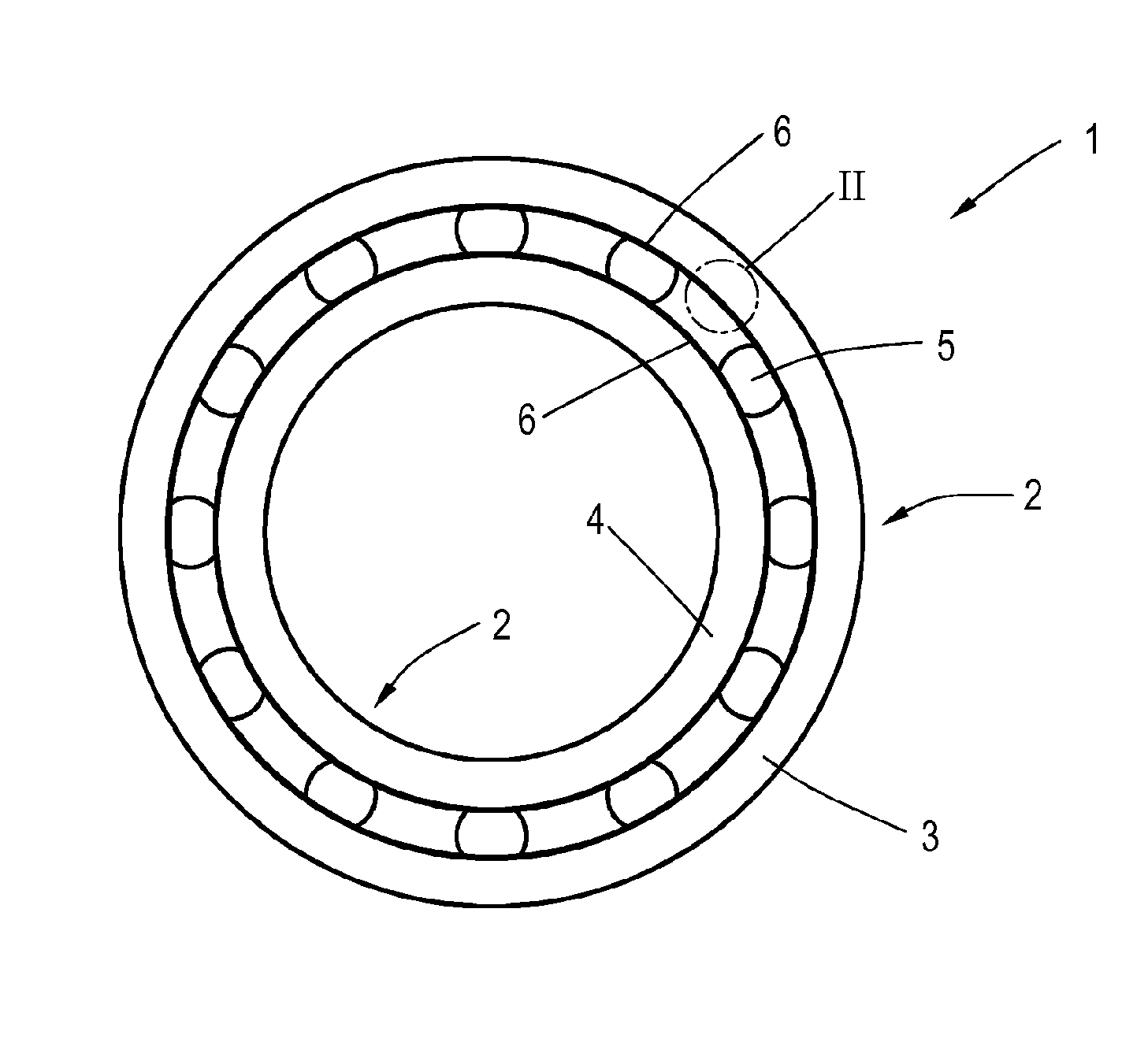
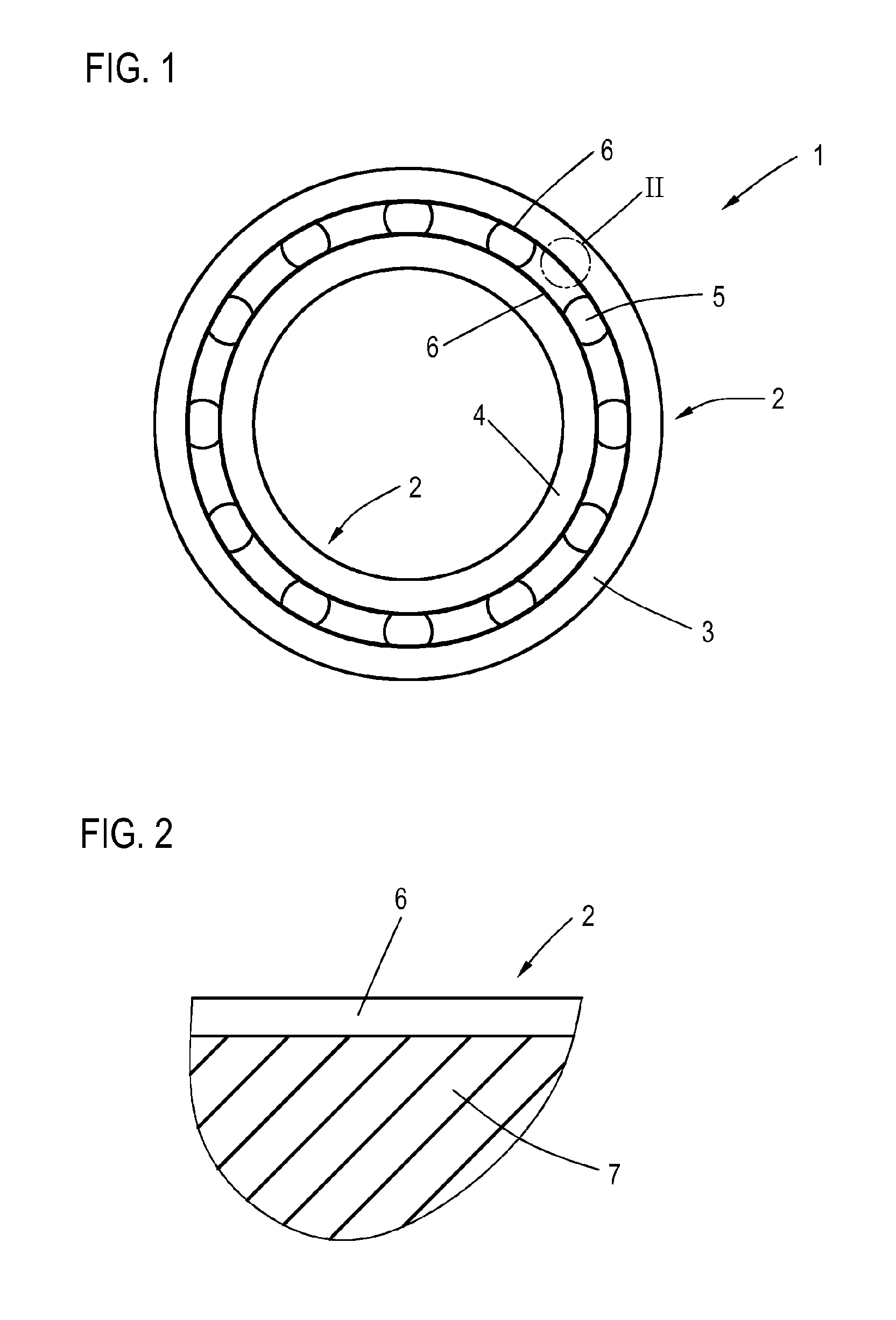
[0050]FIG. 1 shows a rolling bearing 1, including multiple rolling bearing elements 2 according to one exemplary specific embodiment of the present invention. Rolling bearing 1 is apparently provided as a ball bearing. Rolling bearing elements 2 are designed as rolling bearing rings 3, 4, between which rolling bodies 5 roll.

[0051]Rolling bearing elements 2, which are designed as rolling bearing rings 3, 4, are manufactured from an austenitic steel, this steel having a composition of 16-21 mass-% chromium, 16-21 mass-% manganese, 0.5 to 2.0 mass-% molybdenum, a total of 0.8 to 1.1 mass-% carbon and nitrogen, the ratio of carbon to nitrogen being 0.5 to 1.1, up to 2.5 mass-% melting-related impurities, and a remainder of mass-% of iron, the total of all components resulting in 100 mass-%.

[0052]Alternatively, one of rolling bearing elements 2 or both rolling bearing elements 2 may also be made of an austenitic steel, which has a composition of 16-21 mass-% chromium, 16-21 mass-% mangan...


PUM

PropertyMeasurementUnit
Temperatureaaaaaaaaaa

Abstract

A rolling bearing element (2), in particular a rolling bearing ring (3, 4), the rolling bearing element being made of an austenitic steel which has a composition of 16-21 mass percent chromium, 16-21 mass percent manganese, 0.5 to 2.0 mass percent molybdenum, a total of 0.8 to 1.1 mass percent carbon and nitrogen, wherein the ratio of carbon to nitrogen is 0.5 to 1.1, up to 2.5 mass percent melting-related impurities, and a remaining mass percent of iron is provided. The sum of all the components equals 100 mass percent, and the rolling bearing element has a surface layer (6) which is produced by at least one measure for diffusing carbon and / or nitrogen into regions near the surface of the rolling bearing element and which contains carbon and / or nitrogen.

Description

[0001]The present invention relates to a rolling bearing element, in particular a rolling bearing ring, this rolling bearing element being formed from an austenitic steel.BACKGROUND[0002]Rolling bearings or rolling bearing elements, such as, in particular, rolling bearing rings, rolling bodies, rolling body cages which accommodate rolling bodies, etc., are known to be used in different fields of technology. Corresponding rolling bearing elements are regularly subjected to high mechanical and / or corrosive stresses during operation.[0003]Known rolling bearing elements are formed, for example, from non-rusting, martensitic rolling bearing steels having carbide phases intercalated therein, which do not have sufficient corrosion resistance against corrosive media, however. Rolling bearing elements made of higher-alloyed steels display an improved corrosion resistance against corrosive media; however, they generally have worse mechanical properties, in particular relating to the wear resi...

Claims


Application Information

Patent Timeline
IPC IPC(8): F16C33/64C23C8/22F16C33/62C23C8/26
CPCF16C33/64F16C33/62C23C8/22C23C8/26C21D9/40C22C38/001C22C38/22C22C38/38C23C8/32C23C8/38F16C19/06F16C33/32F16C2202/04F16C2204/62F16C2204/70F16C2204/74F16C2223/12F16C2223/14F16C2223/16F16C2240/06F16C2240/40F16C2240/60F16C2300/42F16C33/34
Inventor SCHULTE-NOELLE, CHRISTIAN
Owner SCHAEFFLER TECH AG & CO KG
Learn More