
Large fov phase contrast imaging based on detuned configuration including acquisition and reconstruction techniques

a contrast imaging and fov phase technology, applied in the field of digital xray imaging methods/systems, can solve the problems of limiting the application of synchrotron radiation or a well defined monochromatic radiation source, limiting the achievable spatial resolution, and difficult separation between soft tissue materials

Active Publication Date: 2015-07-02
CARESTREAM HEALTH INC
View PDF7 Cites 34 Cited by
  • Summary
  • Abstract
  • Description
  • Claims
  • Application Information

AI Technical Summary

Benefits of technology

The patent text describes methods and devices to improve the use of PCI imaging devices. One aspect is to provide methods to reduce the impact of stationary objects and moving fringe patterns in the images. Another method is to create an absorption image, dark field image, differential phase image, and integrated phase image using a series of digital shifts. These improvements can improve the accuracy and quality of PCI imaging devices.

Problems solved by technology

While generally good contrast between highly attenuating (e.g., hard) and weakly attenuating (e.g., soft) materials is observed, the separation between soft-tissue materials can be difficult because of a low relative contrast.
However, there are various practical problems associated with all three techniques.
In the case of crystal interferometers and diffractometers, high temporal coherence (i.e., a high degree of monochromaticity) is required, which, in result, limits the application to a synchrotron radiation or a well defined monochromatic radiation source.
In addition to requirement of synchrotron source, the use of multi-hole collimator in DEI limits the achievable spatial resolution and increases the acquisition time.
The free-space propagation technique can be limited in efficiency because of a requirement of high spatial coherence, which only can be obtained from an x-ray source with a very small focal spot size, or large propagation distance.
In addition, thermal expansion and / or compression of flexures holding the stepping grating can easily result in displacement of over a hundred of nanometers per Celsius degree.

Method used


Image

  • Large fov phase contrast imaging based on detuned configuration including acquisition and reconstruction techniques
  • Large fov phase contrast imaging based on detuned configuration including acquisition and reconstruction techniques
  • Large fov phase contrast imaging based on detuned configuration including acquisition and reconstruction techniques

Examples


Embodiment Construction

[0033]The following is a description of exemplary embodiments of the invention, examples of which are illustrated in the accompanying drawings. Wherever possible, the same reference numbers will be used throughout the drawings to refer to the same or like parts.

[0034]For illustrative purposes, principles of the invention are described herein by referring mainly to exemplary embodiments thereof. However, one of ordinary skill in the art would readily recognize that the same principles are equally applicable to, and can be implemented in, all types of radiographic imaging arrays, various types of radiographic imaging apparatus and / or methods for using the same and that any such variations do not depart from the true spirit and scope of the application. Moreover, in the following description, references are made to the accompanying figures, which illustrate specific exemplary embodiments. Electrical, mechanical, logical and structural changes can be made to the embodiments without depa...


PUM


Abstract

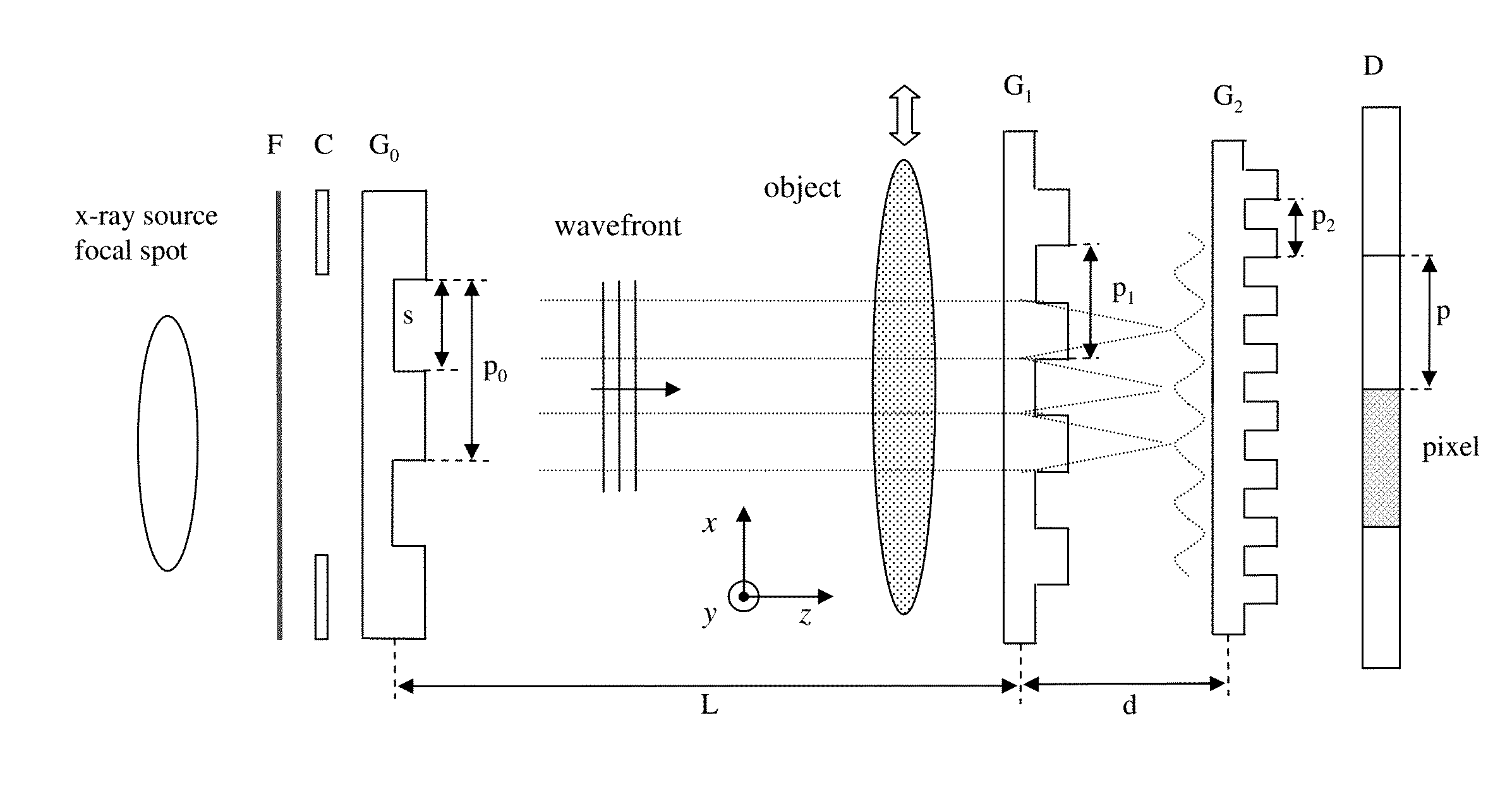
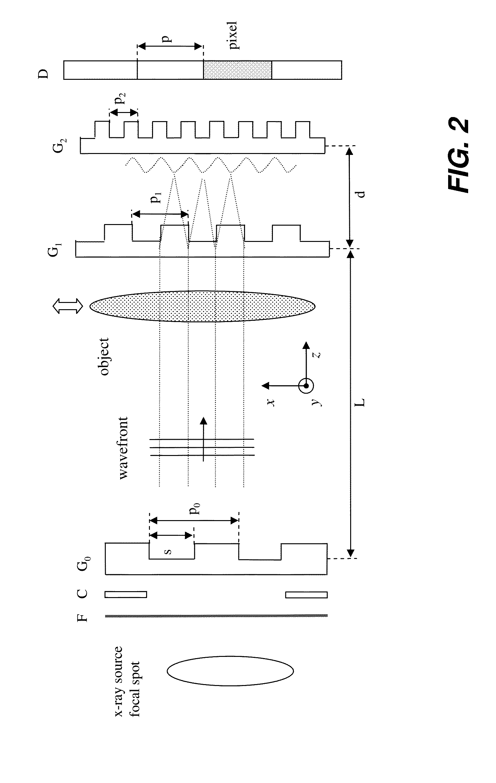
Embodiments of methods and apparatus are disclosed for obtaining a phase-contrast digital imaging system and methods for same that can include an x-ray source for radiographic imaging; a beam shaping assembly, an x-ray grating interferometer including a phase grating and an analyzer grating; and an x-ray detector; where the source grating, the phase grating, and the analyzer grating are detuned and a plurality of uncorrelated reference images are obtained for use in imaging processing with the detuned system.

Description

FIELD OF THE INVENTION[0001]The application generally relates to digital x-ray imaging methods / systems, and more specifically, to methods and / or systems for acquiring multiple image information of an object (e.g., medical radiographic imaging) using a grating-based differential phase contrast imaging technique.BACKGROUND[0002]Conventional medical x-ray imaging devices employ absorption information to probe the interior structure of imaged objects. While generally good contrast between highly attenuating (e.g., hard) and weakly attenuating (e.g., soft) materials is observed, the separation between soft-tissue materials can be difficult because of a low relative contrast. For example, the low-contrast soft tissue materials include, but are not limited to vessels, cartilages, lungs, and breast tissues, which provide poor contrast in comparison to highly attenuating bone structures. In the recent years, interferometric x-ray imaging devices have been introduced to address soft-tissue im...

Claims


Application Information

Patent Timeline
IPC IPC(8): A61B6/00
CPCA61B6/484A61B6/4291A61B6/0487A61B6/06A61B6/4035A61B6/5205A61B6/54G01N23/041G01N23/20075G01N2223/427G01N2223/6126G03H5/00G21K2207/005
Inventor BATURIN, PAVLOSHAFER, MARK E.
Owner CARESTREAM HEALTH INC
Learn More