
Method and apparatus for short circuit protection of power semiconductor switch

a technology of short circuit protection and power semiconductor, which is applied in the direction of circuit arrangements, semiconductor devices, electrical equipment, etc., can solve the problems of high mechanical stress, increase the response time of short circuit protection systems, and abrupt rise in the junction temperature of switches

Inactive Publication Date: 2015-06-04
ABB OY
View PDF6 Cites 22 Cited by
  • Summary
  • Abstract
  • Description
  • Claims
  • Application Information

AI Technical Summary

Benefits of technology

The present disclosure describes a method that allows for quick detection and shutdown of short circuits, reducing the energy involved and minimizing damage to switches. This method does not require current sensors and allows for effective limitation and fast turn-off of short circuits. It also results in reduced on-state conduction losses during normal operation by increasing the gate-emitter voltage. Overall, this method provides savings in cost and service time.

Problems solved by technology

However, the measurement of the VCE,SAT requires a settling time which can increase the response time of the short circuit protection system.
Such a delay can cause an abrupt rise in the junction temperature of the switch.
This can cause high mechanical stress in the semiconductor, which can even cause the switch to explode.
A possibility of such an uncontrolled failure naturally reduces the reliability of the converter.
However, turning off the semiconductor before the stable state is achieved can also generate stress and induce even destruction of the device.
By using this approach, the increase in the current due to a short circuit can be limited.
On the other hand, the control electrode can be unnecessarily de-charged even if there is no short circuit.
This can increase losses during normal operation.
Implementation of any of the above-mentioned approaches can cause additional expenses in material, development and manufacturing costs, making service more complicated and difficult.

Method used


Image

  • Method and apparatus for short circuit protection of power semiconductor switch
  • Method and apparatus for short circuit protection of power semiconductor switch
  • Method and apparatus for short circuit protection of power semiconductor switch

Examples


Embodiment Construction

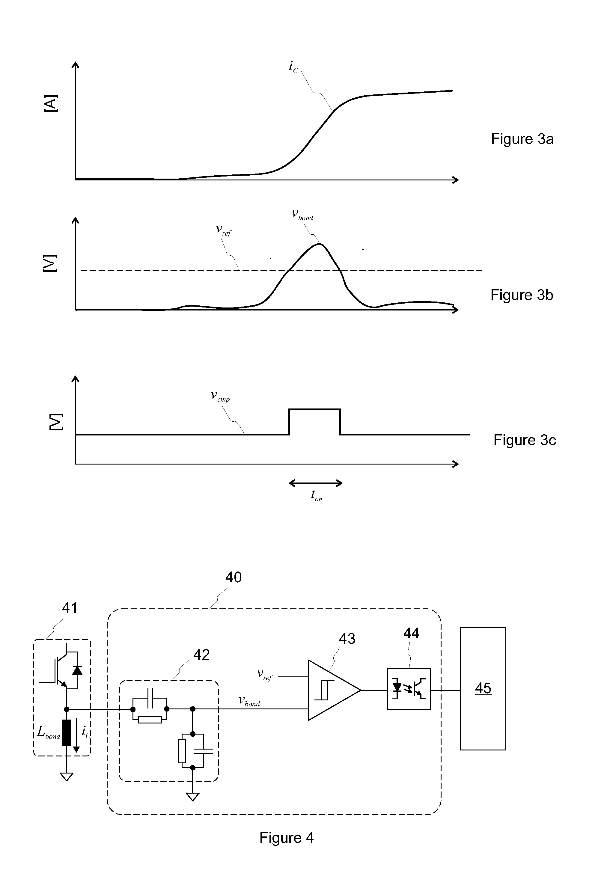
[0024]Exemplary embodiments of the present disclosure provide a method and an apparatus for implementing the method which alleviate the above disadvantages associated with known techniques. Exemplary embodiments of the present disclosure provide a method and an apparatus for a power semiconductor switch, where a current through the switch is responsive to a control terminal voltage at a control terminal of the switch, and the control terminal voltage is driven by a driver unit. Exemplary features of the method and apparatus of the present disclosure are described below.

[0025]The method and apparatus of the present disclosure each achieve an object of providing short circuit protection for a power semiconductor switch (e.g., IGBT, MOSFET, etc.). According to an exemplary embodiment, the method can include steps of detecting a short circuit of a power semiconductor switch, reducing the maximum level of a control terminal voltage (e.g., a gate-emitter voltage in IGBT) in order to limit...


PUM


Abstract

A method and apparatus are provided for a power semiconductor switch. A current through the switch is responsive to a control terminal voltage at a control terminal of the switch, and the control terminal voltage is driven by a driver unit. The method includes measuring or estimating the current based on a bond voltage of the switch, detecting a short circuit by comparing the measured or estimated current to a short circuit current limit, controlling an on-state voltage level of the control terminal voltage based on the comparison to limit the current through the switch during the short circuit, and controlling the control terminal voltage to an off-state voltage level to turn the switch off. The on-state voltage level voltage is controlled by pulse-width modulating the output of the driver unit. A switching frequency of the modulation is at least the cut-off frequency of low-pass characteristics of the control terminal.

Description

RELATED APPLICATION[0001]This application claims priority to European Application 13195668.2 filed in Europe on Dec. 4, 2013. The entire contents of this application are hereby incorporated by reference in their entirety.FIELD[0002]The present disclosure relates to short circuit protection of power semiconductor switches.BACKGROUND INFORMATION[0003]Power converters are used in a wide variety of applications. A power converter may include one or more semiconductor switches which are used to convert power from one form to another. For example, a DC voltage can be converted to an AC voltage or voltages.[0004]In order to perform the conversion, each of the switches in a power converter may be controlled into one of two states: an on-state (i.e. a conductive state) and an off-state (i.e. a non-conductive state). Therefore, turning a switch on means, in this context, setting the switch to the on-state. Accordingly, turning a switch off means setting the switch to the off-state.[0005]Appli...

Claims


Application Information

Patent Timeline
IPC IPC(8): H02H3/08
CPCH02H3/08H03K17/0822
Inventor ALVAREZ VALENZUELA, RODRIGO ALONSOLIZAMA, IGNACIOBERNET, STEFFENLAITINEN, MATTI
Owner ABB OY
Learn More