Novel method for real time tests and diagnosis of partial discharge sources in high voltage equipment and installations, which are in service or out of service, and physical system for the practical use of the method

Inactive Publication Date: 2015-04-30
UNIV MADRID POLITECNICA
View PDF5 Cites 22 Cited by
  • Summary
  • Abstract
  • Description
  • Claims
  • Application Information

AI Technical Summary

Benefits of technology

The present invention describes a new and faster method for diagnosing partial discharges (PDs) in high voltage equipment. This allows for real-time monitoring and improvements in processing time. The method can be used with both the high voltage power grid and a novel voltage source designed for this purpose. The technology also allows for identifying different focal points of PDs and improves the overall condition of high voltage equipment.

Problems solved by technology

The practical difficulties in partial discharge measurements in equipment and installations proposed to be solved by the present invention are:On one hand, the high calculation and analysis time consumption which powerful and complex numerical tools require for applying the mathematical algorithms for discriminating the interfering electric noise masking the electric PD signals due to defects in the high voltage insulation.On the other hand, the difficulty in identifying and discriminating the total number of the PD sources for the purpose of separating them from one another and being able to identify each of them with the defect originating it.And finally, the difficulty in generating high test voltages with alternating voltage waveforms of the same frequency as the grid service frequency (50 Hz or 60 Hz) without requiring large volume and heavy generators.
The drawback of this method is that sometimes the smallest noise signal band coincides with the band where the PD signal is also weak in amplitude, so PD measurement is difficult.
The specific drawback of this method is that the processing is performed by signal level, such that to assure the capture of PD signals the acquisition level must be reduced, and therefore the noise signal content considerably increases.
Processing becomes very laborious because the noise is put together with the PDs.
None of these methods is efficient for white noise, the spectrum of which covers all the frequencies of the PD signal.
Frequency filtering techniques cannot be applied because the PD signal would also be lost, and a noiseless frequency band cannot be chosen either because there is a noise signal in all of them and PD clusters having a frequency different from that of the noise cannot be distinguished either.
The huge drawback of this technique for real time measurements is the high numerical processing time consumption of the recorded signals for discriminating noise from the PDs.
The efficacy of these methods for identifying and discriminating different PD sources is limited by the uncertainty in the location of the PD source, which can be a few metres, such that it is impossible to assure that there is only one PD source in a specific location (for example in a cable termination accessory), one PD source being able to mask others located nearby.
This is particularly critical when the predominating PD source is associated with a danger-free phenomenon, such as for example corona in air, other PD sources co-existing close to it having a smaller amplitude but a higher risk of failure, such as defects inside the insulation for example.
However, when there are several defects, their corresponding patterns can overlap and be easily confused with one another, without it being easy to identify each and every one of them, the operator's experience being crucial for a correct diagnosis.
Additionally, the noise not removed in many commercial techniques makes the identification of different PD sources through the simple visual observation of their patterns of PDs even more difficult.
The drawback of this technique is that the generated alternating voltage wave duration is hundreds of times higher if it is 0.1 Hz or thousands of times higher if it is 0.01 Hz than the sinusoidal wave duration of 50 Hz or 60 Hz of the power grid where the high voltage equipment and installations operate.
The limitation of this technique is that the maximum oscillating test voltage is applied only in the first crest of the voltage.
The drawback of these systems is the required weight and volume.

Method used


Image

  • Novel method for real time tests and diagnosis of partial discharge sources in high voltage equipment and installations, which are in service or out of service, and physical system for the practical use of the method
  • Novel method for real time tests and diagnosis of partial discharge sources in high voltage equipment and installations, which are in service or out of service, and physical system for the practical use of the method
  • Novel method for real time tests and diagnosis of partial discharge sources in high voltage equipment and installations, which are in service or out of service, and physical system for the practical use of the method

Examples


Embodiment Construction

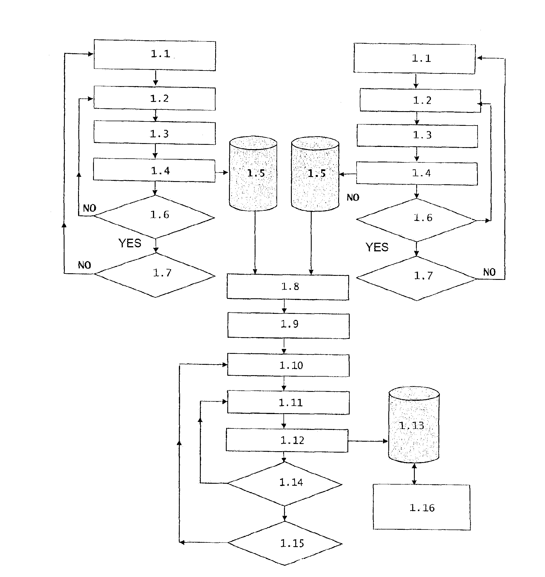
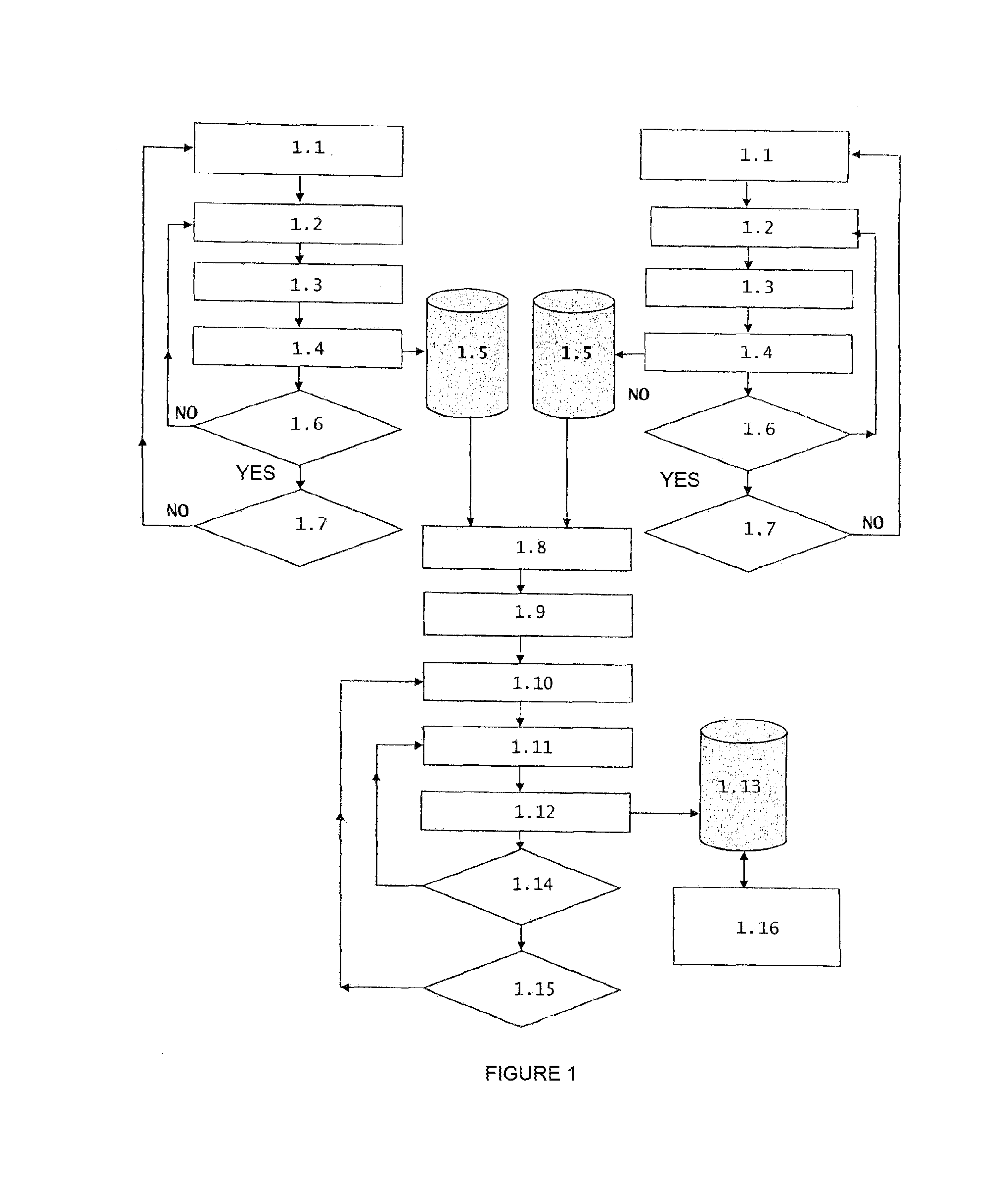
[0032]As mentioned above, the present invention consists of a method for measuring and analysing the measurement, for a real time evaluation of the insulation condition of high voltage cables during their operation in the grid or when they are not connected to the network, which improves the techniques used today and corrects the drawbacks associated with these techniques as stated.

[0033]The objective of the present invention is to provide a new method for measuring and analysing the measurement of partial discharges for the real time evaluation of the insulation condition of high voltage machines, apparatuses, equipment and installations such as insulated cables, either during their normal operation in the grid or out of service in the grid, by means of using a test generator specifically designed for applying the indicated new method for measuring and analysing.

[0034]The present invention allows reducing the time necessary for analysing the measurement, for the purpose of performi...


PUM


Abstract

A method for detecting events associated with partial discharges (PDs) in high voltage equipment and installations diagnoses insulation conditions in real time by using PD signal noise discrimination by the parallel use of multiprocessors, which are additionally used for the discrimination, in real time, of different PD sources located in a single position or in different positions. In order to identify the various PD sources, three-dimensional clusters are formed using the coordinates of three parameters characteristic of each pulse: the parameter associated with the front time of the impulse, the parameter associated with the tail time and the parameter associated with the pulse frequency. The diagnostic method can be performed with grid voltage or independent generators as a voltage source, and the invention particularly relates to a novel voltage source designed therefor. A system for the implementation of the method captures PDs, and performs the necessary analysis and measurement.

Description

OBJECT OF THE INVENTION[0001]The present invention relates to a new diagnostic method for diagnosis of partial discharges (PDs) which complements the methods and systems for the continuous monitoring of (PDs) permanently installed in high voltage equipment or installations and consuming longer calculation time periods for analysing the measurements. The new invention reduces the analysis time, which allows performing real time diagnoses of the insulation condition of high voltage equipment and installations. Additionally, the new invention allows performing the diagnosis either by using the high voltage power grid itself (measurements in service) or with a novel voltage source designed therefor (measurements out of service) as a voltage source. The term high voltage equipment must be understood as a voltage and / or alternating or direct current generator, power transformer, voltage and / or current measurement and / or protection transformer, control switchgear, insulators and surge arre...

Claims


Application Information

Patent Timeline
IPC IPC(8): G01R31/02
CPCG01R31/024G01R31/1263G01R31/1272
Inventor GARNACHO VECINO, FERNANDOSANCHEZ-URAN GONZALEZ, MIGUEL ANGELORTEGO LA MONEDA, JAVIER
Owner UNIV MADRID POLITECNICA
Why Eureka
Try Eureka