Shredder and sheet-like-object processing apparatus using the same
- Summary
- Abstract
- Description
- Claims
- Application Information
AI Technical Summary
Benefits of technology
Problems solved by technology
Method used
Image
Examples
first embodiment
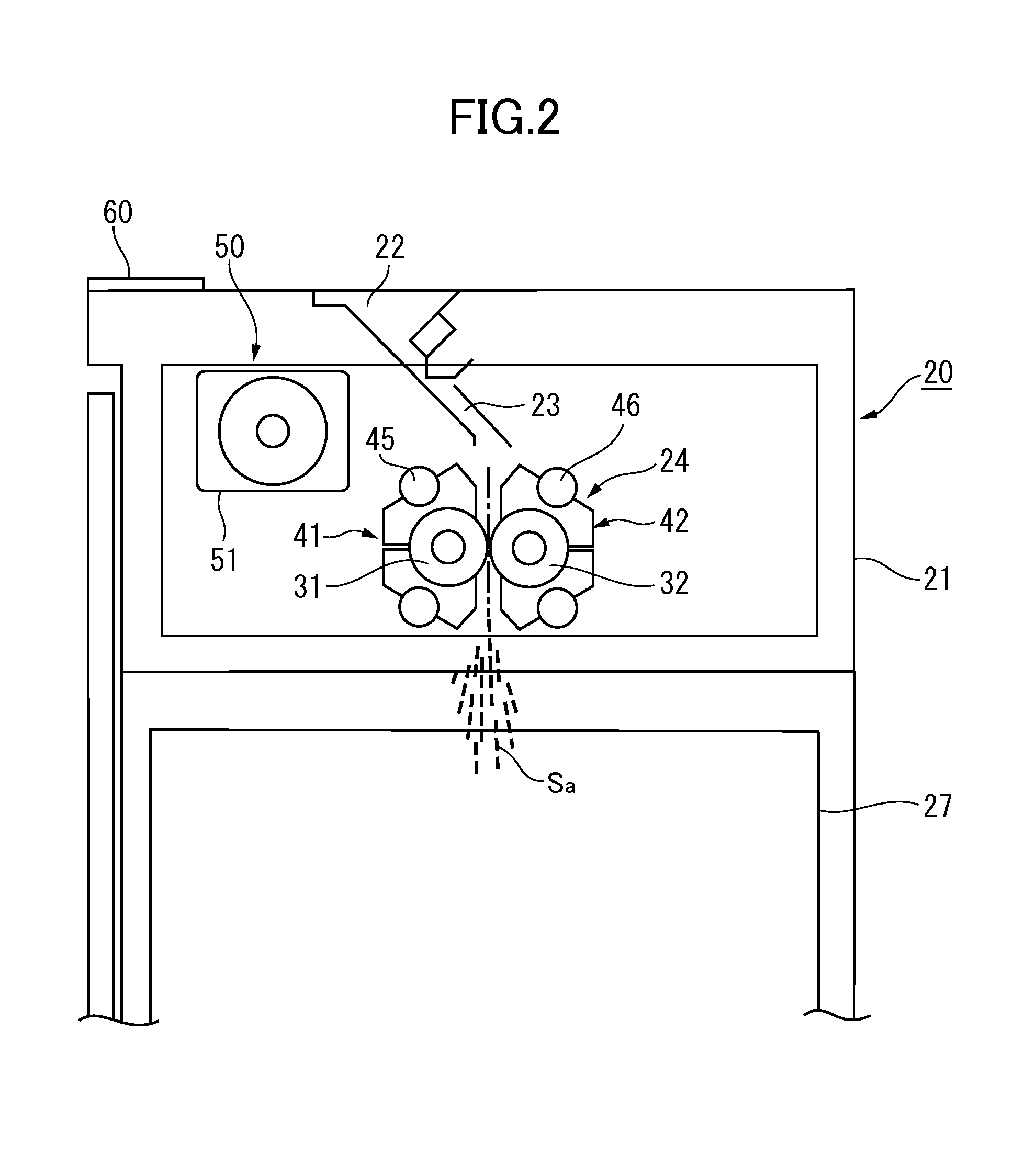
[0073]FIG. 2 illustrates an overall configuration of a shredder according to a first embodiment of the present invention.
[0074]—Overall Configuration of Shredder—
[0075]As illustrated in FIG. 2, a shredder 20 includes a shredder casing 21 having a substantially rectangular parallelepiped shape. A feed port 22 through which sheets as sheet-like objects to be shredded are fed is opened in an upper surface of the shredder casing 21. A conveying path 23 defined by a pair of guide chutes is provided in the feed port 22. A shredding mechanism 24 is arranged in a midway of the conveying path 23. Below the shredding mechanism 24 in the shredder casing 21, a trash container 27 for receiving particles of the sheets is arranged so as to be removable.
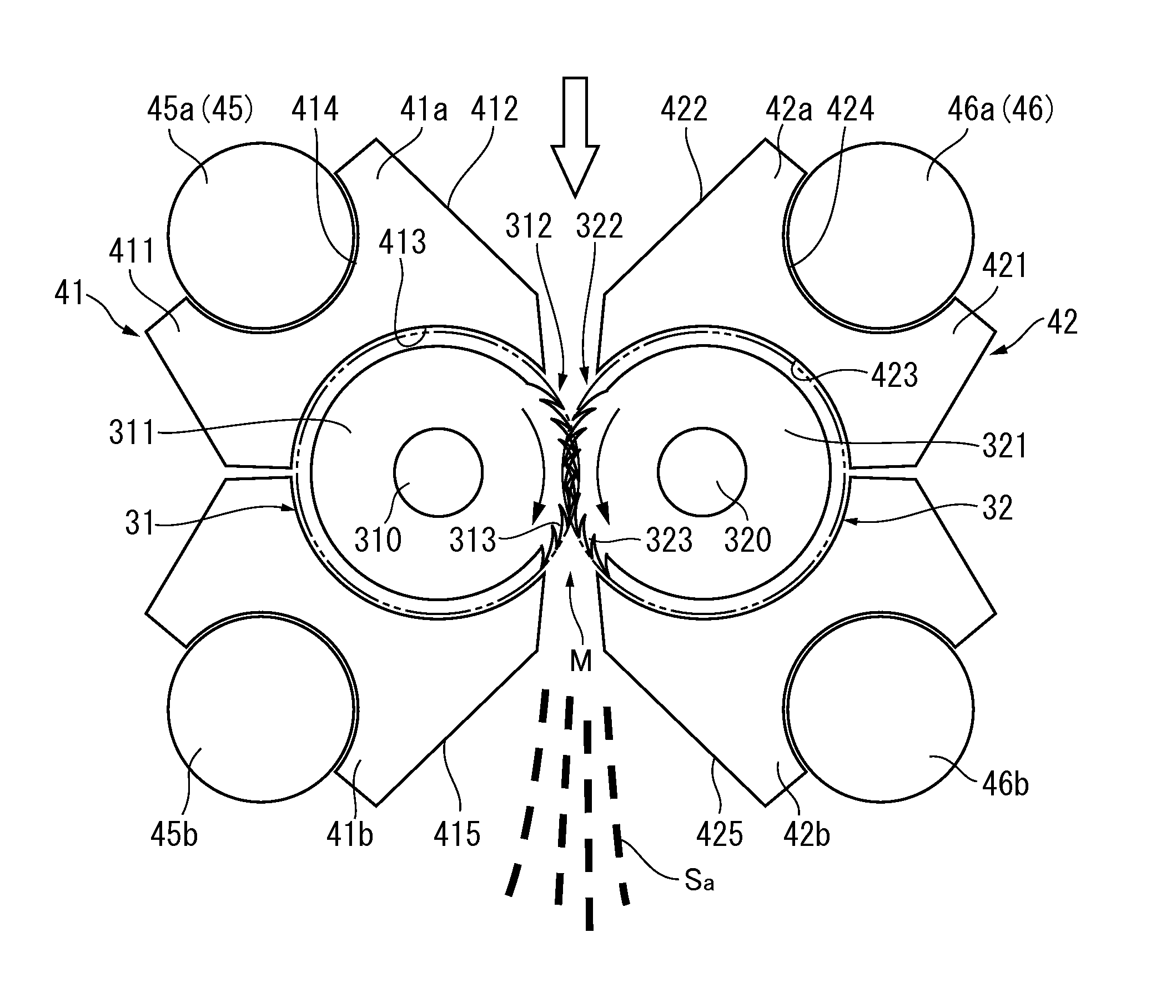
[0076]Specifically, the shredding mechanism 24 employs a cross-cut type using blade drums 31 and 32 in a pair as cutter elements. With this, when the sheets are inserted through a meshing region between the blade drums 31 and 32 in a pair, the sheet...
second embodiment
[0129]FIG. 10 illustrates a main part of the shredding mechanism 24 of the shredder according to a second embodiment of the present invention.
[0130]In the shredding mechanism 24 according to this embodiment, the blade drums 31 and 32 in a pair are substantially the same as those in the first embodiment, but the scrapers 41 and 42 as scraping members are different from those in the first embodiment.
[0131]In this embodiment, the scrapers 41 include first partition members 41e provided so as to surround substantially left half of the first blade drum 31, that is, surround an opposite side of the meshing region M between the blade drums 31 and 32 in a pair, and provided correspondingly to the recessed portions 315 between the cutter portions 312 of the first blade drum 31, and second partition members 41f arranged between the first partition members 41e correspondingly to the cutter portions 312 of the first blade drum 31.
[0132]Note that, as illustrated in FIGS. 10 and 11, the first par...
third embodiment
[0164]FIG. 16 is an explanatory view of a main part of an image forming apparatus according to a third embodiment of the present invention.
[0165]In FIG. 16, an image forming apparatus 200 has an apparatus casing 210 in which the shredder 20 is installed.
[0166]In this embodiment, the image forming apparatus 200 has a basic configuration in which the apparatus casing 210 includes therein an image forming unit 220 capable of forming electrophotographic images. Sheets S fed from a sheet feeding tray 230 are conveyed along a predetermined conveying path 213 up to the image forming unit 220, and images formed in the image forming unit 220 are transferred onto the sheets S. Then, the images are fixed to the sheets S by a fixing device 240, for example, of a heating-and-pressing type. Note that, a sheet receiving tray for receiving the sheets S having images formed thereon by a normal image forming process in the image forming unit 220 is denoted by the reference symbol 250.
[0167]Further, t...
PUM
 Abstract
Description
Claims
Application Information
 - R&D
- Intellectual Property
- Life Sciences
- Materials
- Tech Scout
- Unparalleled Data Quality
- Higher Quality Content
- 60% Fewer Hallucinations
Browse by: Latest US Patents, China's latest patents, Technical Efficacy Thesaurus, Application Domain, Technology Topic, Popular Technical Reports.
© 2025 PatSnap. All rights reserved.Legal|Privacy policy|Modern Slavery Act Transparency Statement|Sitemap|About US| Contact US: help@patsnap.com


