Network migration queuing service in a wireless network

a wireless network and network migration technology, applied in the field of large-area broadband networks, can solve the problems of high data rate and increased capacity offered by 3g and 4g networks that do not meet the current and expected demands for bandwidth, are difficult to meet these user demands, and are not enough to supply video services to more than a handful of users, so as to reduce the time-latency of applications, reduce the utilization of communication networks, and reduce the effect of latency

Active Publication Date: 2015-03-19
ALL PURPOSE NETWORKS INC
View PDF7 Cites 63 Cited by
  • Summary
  • Abstract
  • Description
  • Claims
  • Application Information

AI Technical Summary

Benefits of technology

[0008]Ordinarily, a mobile cellular device (e.g., a cell phone) accessing a service though an application server (e.g., streaming a video to the cell phone) via an access control node incurs communication latency associated with traversal across a communication network to the application server. In embodiments, a centralized server (the ‘centralized optimization server’) is deployed in a central location amongst a plurality of access control nodes, and thus reduces the time-latency for applications being run from the mobile device. Further, by placing additional local optimization servers at the access control nodes, application functionality may be optionally transferred from the centralized optimization server to the local optimization server, such as in in

Problems solved by technology

However, the popularity of data applications, and especially of video applications, is becoming so great that even the high data rates and increased capacity offered by 3G and 4G networks do not meet the current and expected demands for bandwidth.
Several factors combine to make it difficult to meet these user demands.
This is not enough to supply video services to more than a handful of users.
Furthermore, inter-cell interference caused by the overlap of RF signals between transmitting Cells reduces the data rates and capacities that may be provided to users who are located in the boundaries between Cells.
Facilities that operate at one Gbps may not be deployed to reach all base stations, and hence, a mo

Method used


Image

  • Network migration queuing service in a wireless network
  • Network migration queuing service in a wireless network
  • Network migration queuing service in a wireless network

Examples


Embodiment Construction

[0075]The following is a written description of the present disclosure, and of the manner and process of making and using it, in such full, clear, concise, and exact terms as to enable any person skilled in the art to which it pertains, or with which it is most nearly connected, to make and use the same, and sets forth the best mode contemplated by the inventors of carrying out the disclosure.

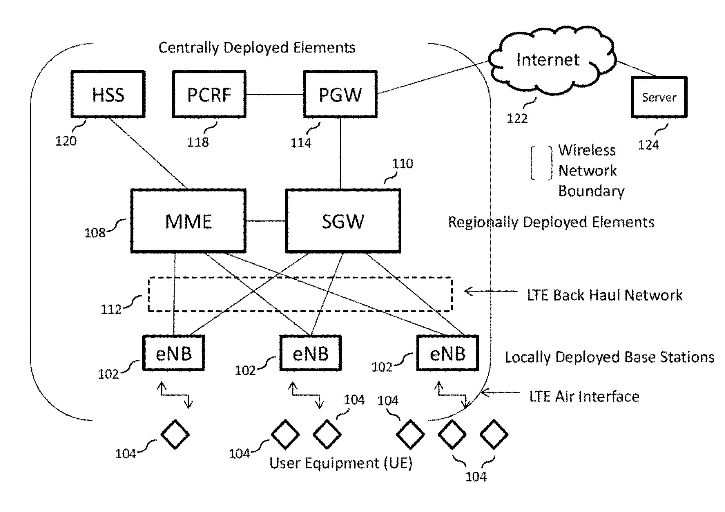
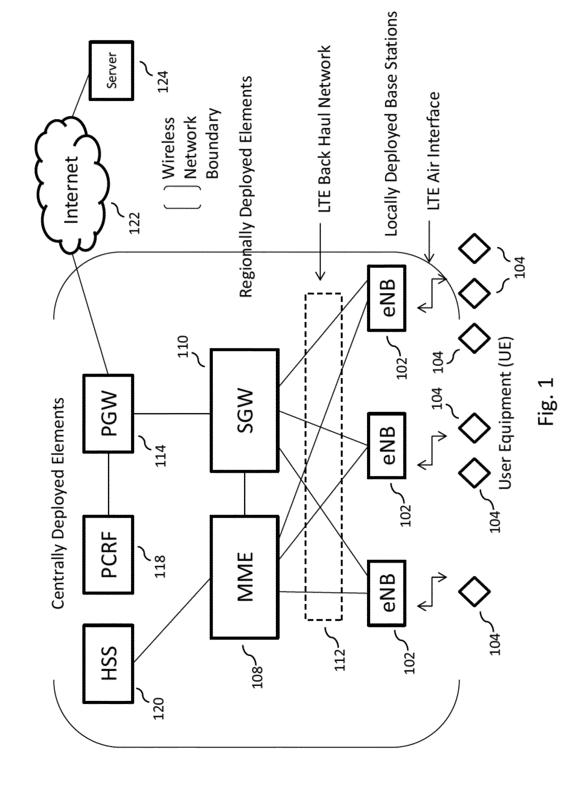
[0076]The present disclosure is related to a broadband wireless network, more specifically, to a multi-purpose network, alternatively referred to in this disclosure as an “All Purpose Network” or “APN,” that is capable of implementing a large scale (e.g., national) broadband wireless network to provide a very high wireless data capacity, and is capable of resolving all the issues described above. The APN may combine proven leading edge commercial wireless design and architecture methodologies with advanced RF technologies to substantially improve spectrum efficiency, spectrum usage, and data pe...


PUM


Abstract

In embodiments of the present disclosure improved capabilities are described for increasing the bandwidth in a wireless communication network, where centralized optimization servers with publish-subscribe broker services are utilized in conjunction with a queuing service application that provides packet service continuity when a mobile device moves between different access control nodes of the wireless communication network, and wherein the queuing service application is connected to a publish/subscribe broker network to receive service packets matching the service packets directed to the mobile device, wherein the service application makes the matching service packets available to the mobile device to replace service packets that the mobile device did not receive during a time in which the mobile device is in transition between being connected to any of the access control nodes.

Description

CROSS-REFERENCE TO RELATED APPLICATIONS[0001]This application is a continuation-in-part of U.S. patent application Ser. No. 14 / 337,657, filed Jul. 22, 2014, which is a continuation-in-part of U.S. patent application Ser. No. 14 / 016,289 filed Sep. 3, 2013, which is a continuation of U.S. patent application Ser. No. 13 / 667,424, filed Nov. 2, 2012, which claims the benefit of the following provisional application: U.S. Provisional Application 61 / 659,174, filed Jun. 13, 2012.[0002]U.S. patent application Ser. No. 14 / 337,657 is also a continuation-in-part of U.S. patent application Ser. No. 13 / 755,808 filed Jan. 31, 2013, which is a continuation in part of U.S. patent application Ser. No. 13 / 667,424, filed Nov. 2, 2012, which claims the benefit of the following provisional application: U.S. Provisional Application 61 / 659,174, filed Jun. 13, 2012; and a continuation-in-part of U.S. patent application Ser. No. 14 / 200,874 filed Mar. 7, 2014, which is a continuation-in-part of U.S. patent ap...

Claims


Application Information

Patent Timeline
IPC IPC(8): H04W28/06H04W28/16H04W12/08
CPCH04W28/06H04W12/08H04W28/16H04W72/04H04W36/023H04W36/02H04W24/02H04W36/165H04L43/0817H04L43/10G06F11/00G06F11/2038G06F11/2097G08C15/00H04B7/04H04B17/00H04L63/0861H04W24/04H04W36/0016H04W36/0033H04W72/0453H04L1/0026H04L1/0027H04W12/06H04W12/088H04L67/56H04L67/568H04W72/541H04L1/00H04W28/021H04W28/0226H04W40/20
Inventor RUBIN, HARVEYBREWINGTON, JAMES KEITHSAWKAR, ANIL S.POTICNY, DAVID M.
Owner ALL PURPOSE NETWORKS INC
Why Eureka
Try Eureka