
Alcohol interlock system with wireless data transmission and safety function

an interlock system and wireless data technology, applied in the direction of alarms, sensors, driver input parameters, etc., can solve the problems of many interlock systems not being used, driver is not able to start his or her vehicle, and cannot be deactivated or reactivated from a remote center

Active Publication Date: 2012-08-14
DRAGER SAFETY
View PDF10 Cites 43 Cited by
  • Summary
  • Abstract
  • Description
  • Claims
  • Application Information

AI Technical Summary

Benefits of technology

Facilitates quicker reaction to driver misconduct, reduces downtime, and allows for remote maintenance and data access, ensuring vehicles can be started or maintained without towing to a workshop, while ensuring only authorized personnel can bypass the interlock system.

Problems solved by technology

One drawback of the prior-art interlock systems is that these cannot be deactivated or reactivated from a remote center.
Many interlock systems are not used to prevent, for example, an offender sentenced because of an alcohol-related offense, from starting his automobile while under the influence of alcohol.
Should the vehicle be prevented from being started, for example, because of a technical defect of the interlock system or due to a malfunction of or erroneous detection by the alcohol sensor, the driver is not able to start his or her vehicle even though the driver is not under the influence of alcohol.
It may therefore happen in case of a sudden malfunction of the interlock system that, for example, a truck transporting hazardous materials cannot be started any more in the middle of the turnpike.
(However, this is possible only if there is no hardware defect, which makes communication with the interlock entirely impossible.)
Both solutions are very time-consuming and lead to high resulting costs.

Method used


Image

  • Alcohol interlock system with wireless data transmission and safety function
  • Alcohol interlock system with wireless data transmission and safety function
  • Alcohol interlock system with wireless data transmission and safety function

Examples


Embodiment Construction

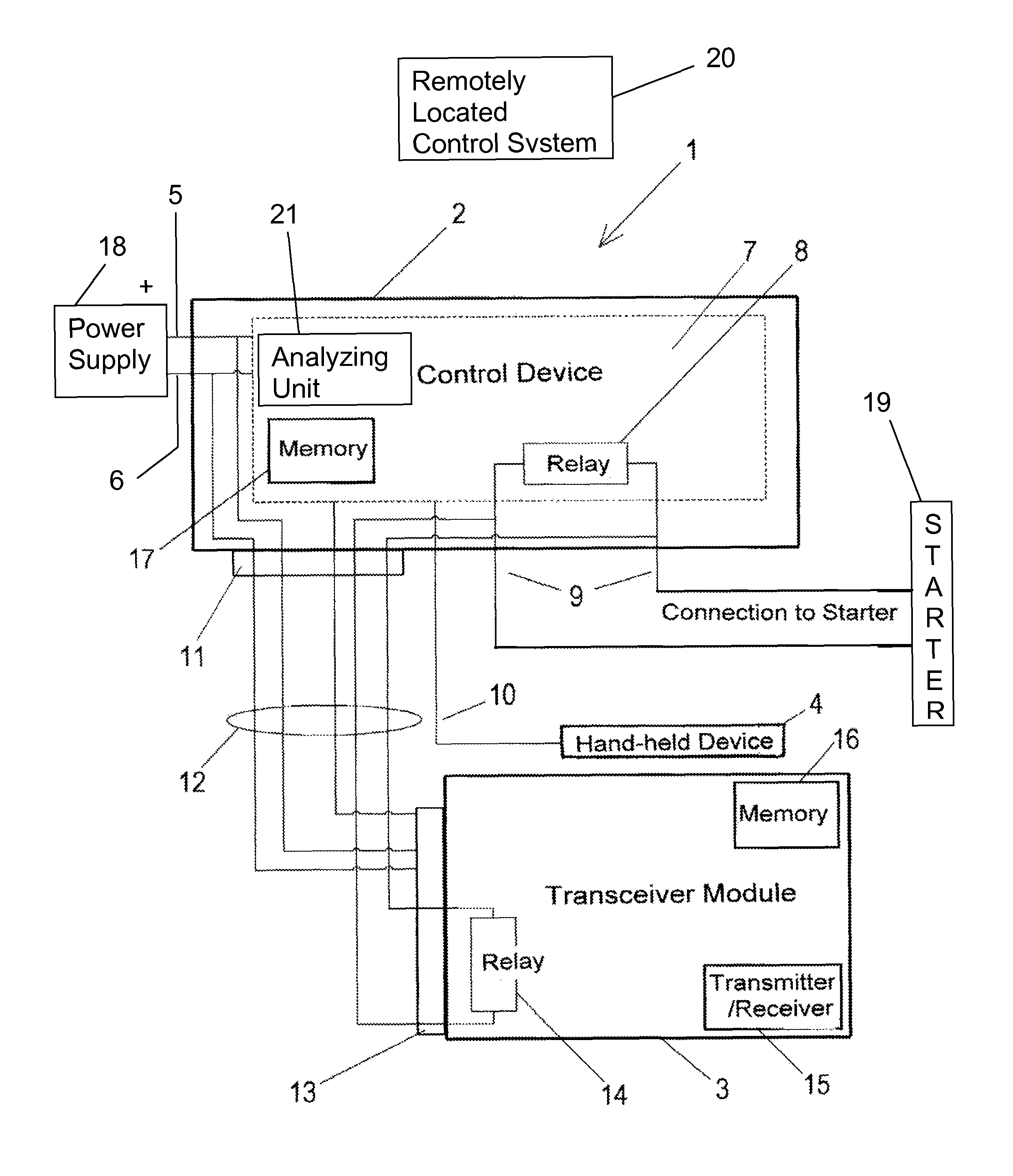
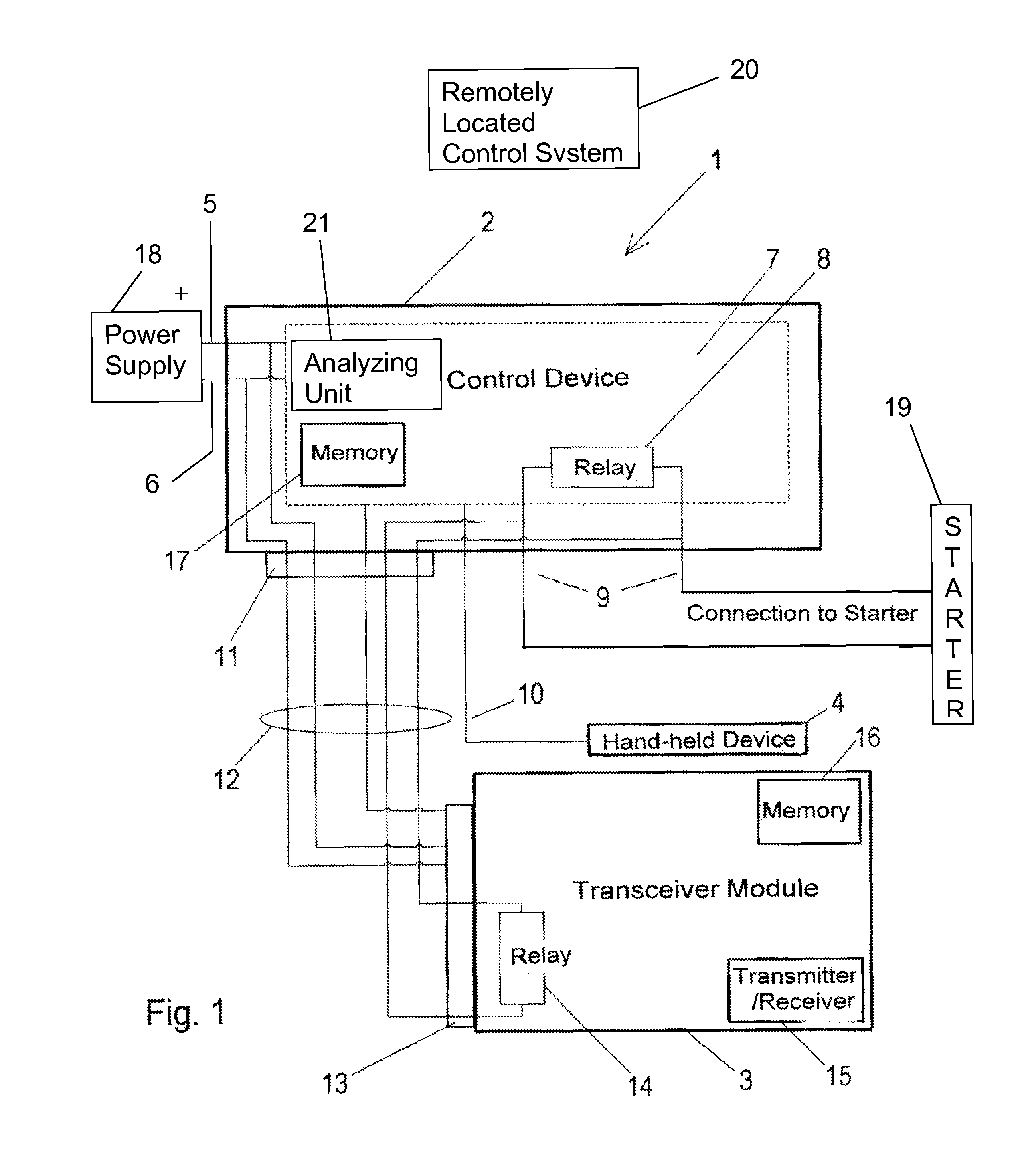
[0028]Referring to the drawings in particular, an interlock system 1 shown in FIG. 1 has essentially a control device 2 coupled with the ignition of a motor vehicle, a module 3 for wireless data transmission and a hand-held device 4 for alcohol testing. The control device 2 is connected via two terminals 5, 6 to the battery or power supply 18 of the vehicle, in which the interlock system 1 is installed. The components of the control device are contained in a stable housing, which is mounted preferably under the dashboard of the vehicle or in another, difficult-to-access and safe area of the vehicle. All essential components of the control device 2 are preferably provided on a printed circuit board 7. These components also include a relay 8 or a corresponding switching means (e.g., thyristor, MOSFET (Metal-Oxide Semiconductor Field-Effect Transistor), etc.), which is preferably integrated via an electric connection 9 in the electric circuit / control circuit of the starter 19 for start...


PUM

PropertyMeasurementUnit
timeaaaaaaaaaa
timeaaaaaaaaaa
voltageaaaaaaaaaa

Abstract

An interlock system (1) for a vehicle is provided with an alcohol tester (4), which is designed to measure the alcohol level of a driver of the vehicle. A control device (2) is coupled with the alcohol tester (4) and is designed to make it possible to start the vehicle or to prevent the vehicle from being started depending on the measured alcohol level. A transceiver module (3) is coupled with the control device (2) and is designed to send data to a remotely located control system in a wireless manner or to receive data from said control system in a wireless manner. The transceiver module (3) is designed, furthermore, to release the control device (2) in response to data received in a wireless manner in order to make it possible to start the vehicle regardless of the operating state of the control device.

Description

CROSS REFERENCE TO RELATED APPLICATIONS[0001]This application claims the benefit of priority under 35 U.S.C. §119 of European Patent Application EP 09 162 775.2 filed Jun. 16, 2009, the entire contents of which are incorporated herein by reference.FIELD OF THE INVENTION[0002]The present invention pertains to a device that is designed to prevent a vehicle from being started or a machine from being operated by a user who is under the influence of alcohol. Such a device is usually called an alcohol interlock system or “interlock” for short and embodies, in general, the combination of an alcohol tester as well as a vehicle immobilizer for a motor vehicle or a blocking means for a machine.BACKGROUND OF THE INVENTION[0003]An interlock system is usually used to prevent a driver who is under the influence of alcohol after a positive result has been obtained for an alcohol test from starting the engine of a vehicle (passenger car, truck, bus, etc.). An interlock system contains for this esse...

Claims


Application Information

Patent Timeline
Patent Type & Authority Patents(United States)
IPC IPC(8): B60K28/06G01N33/497
CPCA61B5/18B60K28/063A61B5/097B60W2540/24
Inventor ZIMMERMANN, MARTINMORLEY, STEFANREINHART, MICHAEL
Owner DRAGER SAFETY
Learn More