
Semiconductor structure and method of forming the same

Active Publication Date: 2015-03-05
UNITED MICROELECTRONICS CORP
View PDF4 Cites 42 Cited by
  • Summary
  • Abstract
  • Description
  • Claims
  • Application Information

AI Technical Summary

Benefits of technology

The present invention provides a method for forming a semiconductor structure by which a multi-layer top barrier structure can be formed to effectively block metal diffusion and improve device performance. The method includes a silicification treatment and a nitridation treatment for the surface of the multi-layer top barrier structure, which results in the formation of TiSiN, ensuring uniform thickness at the bottom corner of the gate trench and providing enough barrier properties. The method is easy and simple to integrate into the existing CMOS process, making it competitive advantage over competitors.

Problems solved by technology

The metal gate usually contains aluminium (Al) or copper (Cu), which is prone to diffusion or electro-migration into surrounding materials and thereby deteriorates the performance of the metal-gate device.
However, such single barrier layer is usually thinner at the bottom corner of the gate trench and incapable of providing enough barrier properties.

Method used


Image

  • Semiconductor structure and method of forming the same
  • Semiconductor structure and method of forming the same
  • Semiconductor structure and method of forming the same

Examples


first embodiment

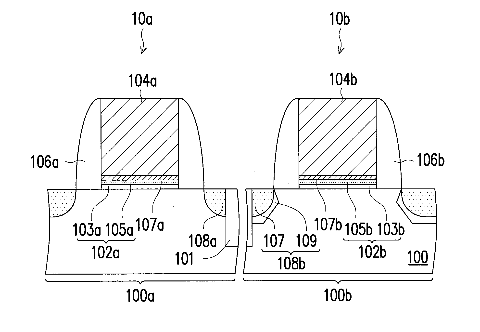
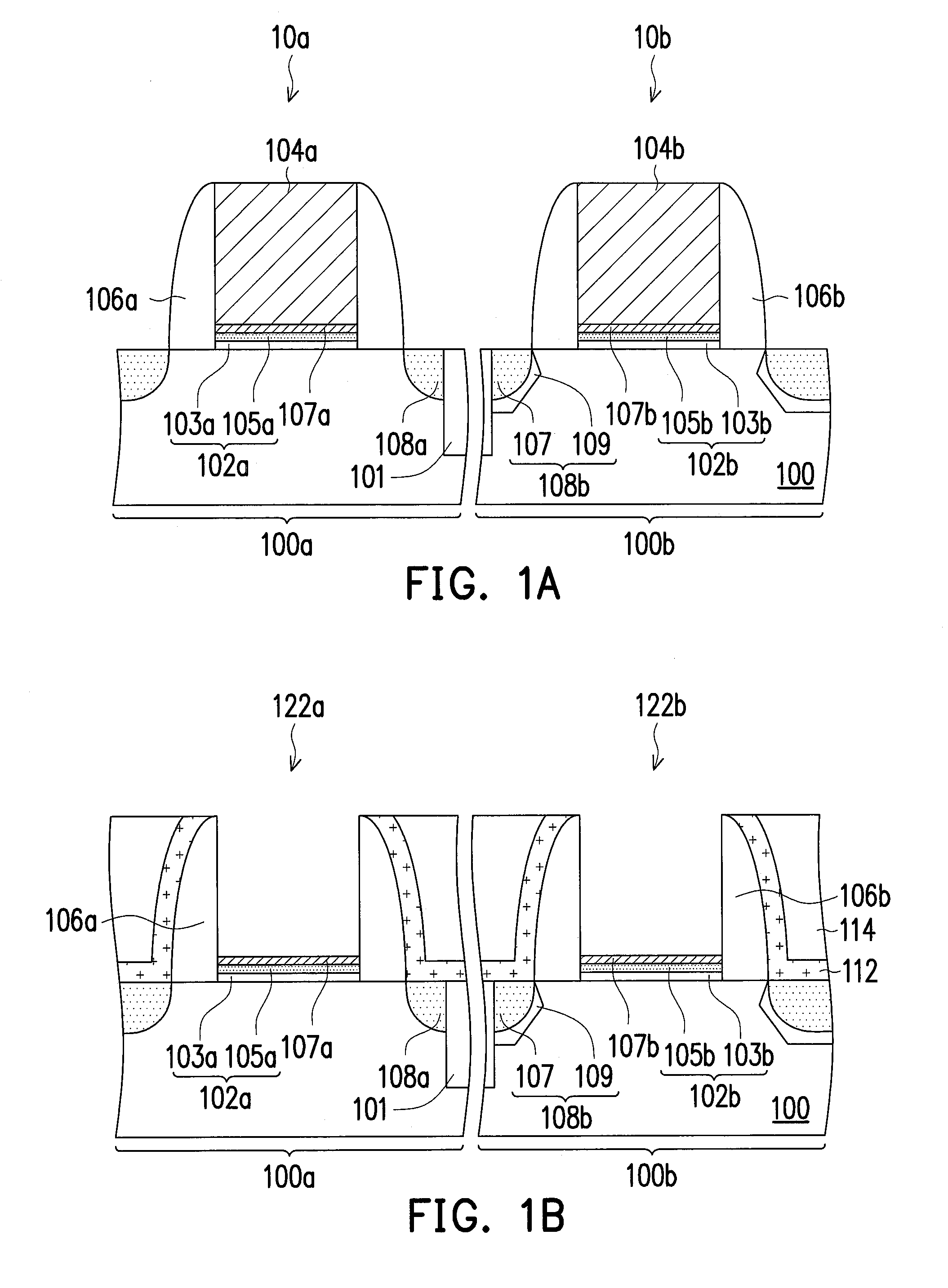
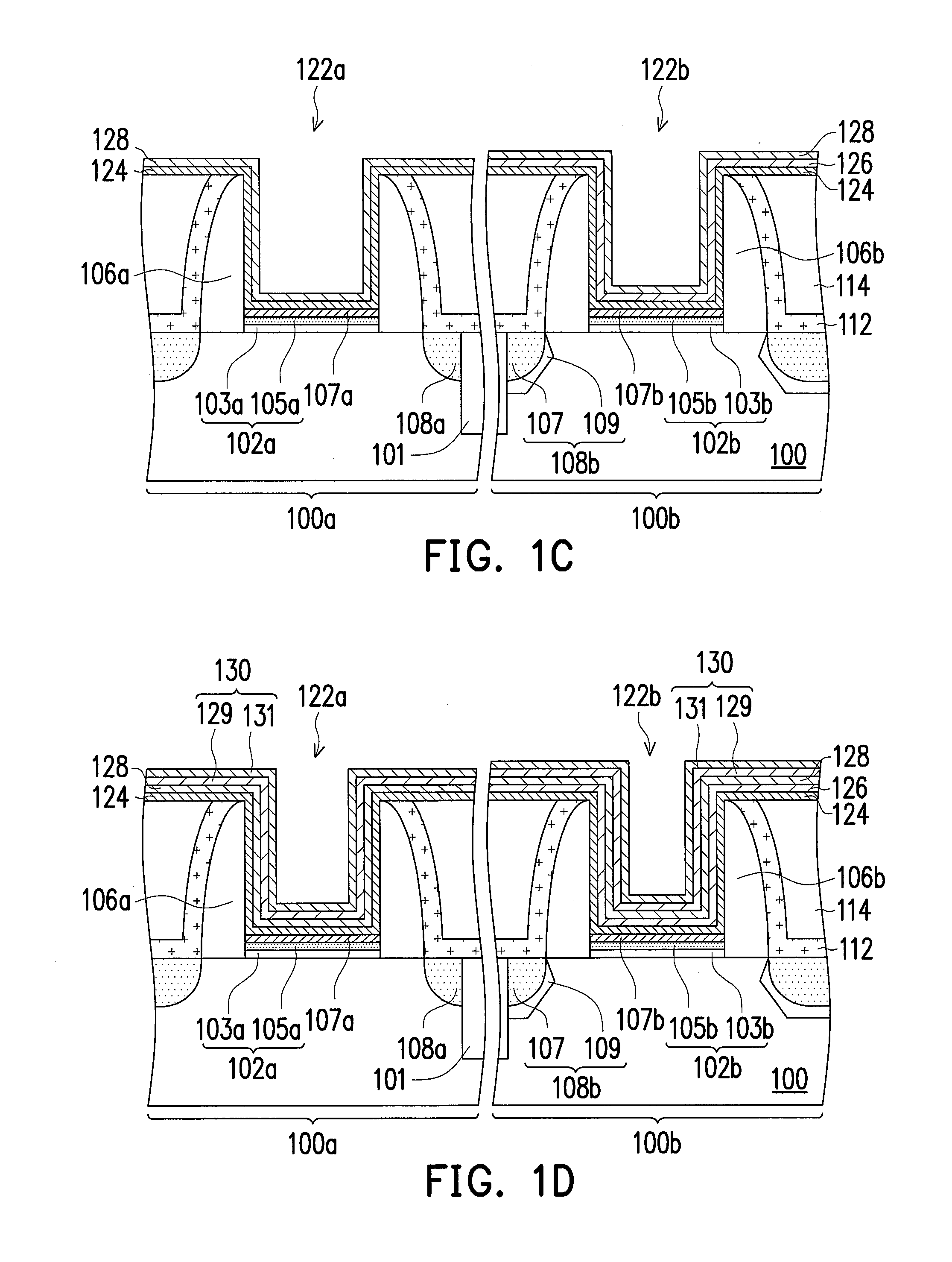
[0033]FIG. 1A to FIG. 1F-1 are schematic cross-sectional views illustrating a method of forming a semiconductor structure according to a first embodiment of the present invention. In this embodiment, the method of the invention is integrated with the “high-k first” process for illustration.

[0034]Referring to FIG. 1A, at least one gate structure is formed on a substrate 100. The substrate 100 can be a semiconductor substrate, such as a silicon substrate. In this embodiment, the substrate 100 has a first area 100a and a second area 100b, and gate structures 10a and 10b are respectively formed in the first and second areas 100a and 100b, but the present invention is not limited thereto. At least one shallow trench isolation (STI) structure 101 is formed in the substrate 100 between the gate structures 10a and 10b for providing electrical isolation. The first and second areas 100a and 100b are for forming semiconductor devices with different conductivity types. In an embodiment, the fir...

second embodiment

[0062]The second embodiment is similar to the first embodiment. The difference between first and second embodiments is described in the following, and the similarities are not iterated herein.

[0063]FIG. 2A to FIG. 2D-1 are schematic cross-sectional views illustrating a method of forming a semiconductor structure according to a second embodiment of the present invention.

[0064]Referring to FIG. 2A, at least one gate structure is formed on a substrate 100. The substrate 100 has a first area 100a and a second area 100b, and gate structures 12a and 12b are respectively formed in the first and second areas 100a and 100b. At least one STI structure 101 is formed in the substrate 100 between the gate structures 10a and 10b for providing electrical isolation. The first and second areas 100a and 100b are for forming semiconductor devices with different conductivity types. In an embodiment, the first area 100a is for forming an N-type device, and the second area 100b is for forming a P-type de...


PUM


Abstract

A method of forming a semiconductor device is disclosed. A substrate having a dielectric layer thereon is provided. The dielectric layer has a gate trench therein and a gate dielectric layer is formed on a bottom of the gate trench. A work function metal layer and a top barrier layer are sequentially formed in the gate trench. A treatment is performed to the top barrier layer so as to form a silicon-containing top barrier layer. A low-resistivity metal layer is formed in the gate trench.

Description

BACKGROUND OF THE INVENTION[0001]1. Field of Invention[0002]The present invention relates to a semiconductor structure and a method of forming the same, and more generally to a semiconductor device having a metal gate and a method of forming the same.[0003]2. Description of Related Art[0004]MOS is a basic structure widely applied to various semiconductor devices, such as memory devices, image sensors and display devices. An electric device is required to be made lighter, thinner and smaller. As the CMOS is continuously minimized, a logic CMOS technology is developed towards a technology having a high dielectric constant (high-k) dielectric layer and a metal gate.[0005]The metal gate usually contains aluminium (Al) or copper (Cu), which is prone to diffusion or electro-migration into surrounding materials and thereby deteriorates the performance of the metal-gate device. A single barrier layer (e.g. TiN) is thus provided to prevent diffusion of metals. However, such single barrier la...

Claims


Application Information

Patent Timeline
IPC IPC(8): H01L29/78H01L29/66
CPCH01L29/66477H01L29/78H01L21/28088H01L21/2855H01L21/823842H01L29/165H01L29/4966H01L29/513H01L29/517H01L29/66545H01L29/66575H01L29/66636
Inventor LIN, CHUN-HSIENCHEN, MIN-HSIEN
Owner UNITED MICROELECTRONICS CORP
Learn More