
Integrated fiber cement and foam as insulated cladding with enhancements

a technology of insulating cladding and fiber cement, which is applied in the field of composite fiber cement cladding, can solve the problems of affecting the aesthetics, water management, other properties of the wall structure assembly, and the design of other components of the wall, so as to improve the insulation capacity of the cladding material, reduce the installation time, and increase the effect of wind load

Active Publication Date: 2015-02-19
JAMES HARDIE TECH LTD
View PDF17 Cites 42 Cited by
  • Summary
  • Abstract
  • Description
  • Claims
  • Application Information

AI Technical Summary

Benefits of technology

The patent text describes a system that combines fiber cement and foam to improve the insulation capacity of cladding materials during construction. The system has various advantages such as reducing installation time, wind load, simplifying assembly, and resisting thermal bridging. The foam layer facilitates alignment and assembly of multiple panels, and also acts as a thermal break and air seal. Additionally, the system can aid in the placement of fasteners, and can be stacked for easy transportation without damaging the foam.

Problems solved by technology

Adding additional wall insulation, however, can drive up the cost of construction as it requires additional material and installation labor.
Adding additional exterior wall insulation can adversely affect the aesthetics, water management, and other properties of the wall structure assembly, as well as impact the design of other components of the wall.
While foamed material has been used as an insulation material in certain building construction, it has not been used as efficiently and effectively as it could be.
As such, the installation of the foam sheathing requires additional processing steps.
The foam installation may also create aesthetic issues with the exterior siding, such as causing a wavy appearance as when siding is installed over deformations in the foam where fasteners compress the underlying foam.
Additionally, in high-wind regions, sidings are frequently blown off walls of building structures.
However, these existing methods for enhancing wind resistance of sidings require additional material and labor, and can detract from the aesthetics of exterior building structure.

Method used


Image

  • Integrated fiber cement and foam as insulated cladding with enhancements
  • Integrated fiber cement and foam as insulated cladding with enhancements
  • Integrated fiber cement and foam as insulated cladding with enhancements

Examples


Embodiment Construction

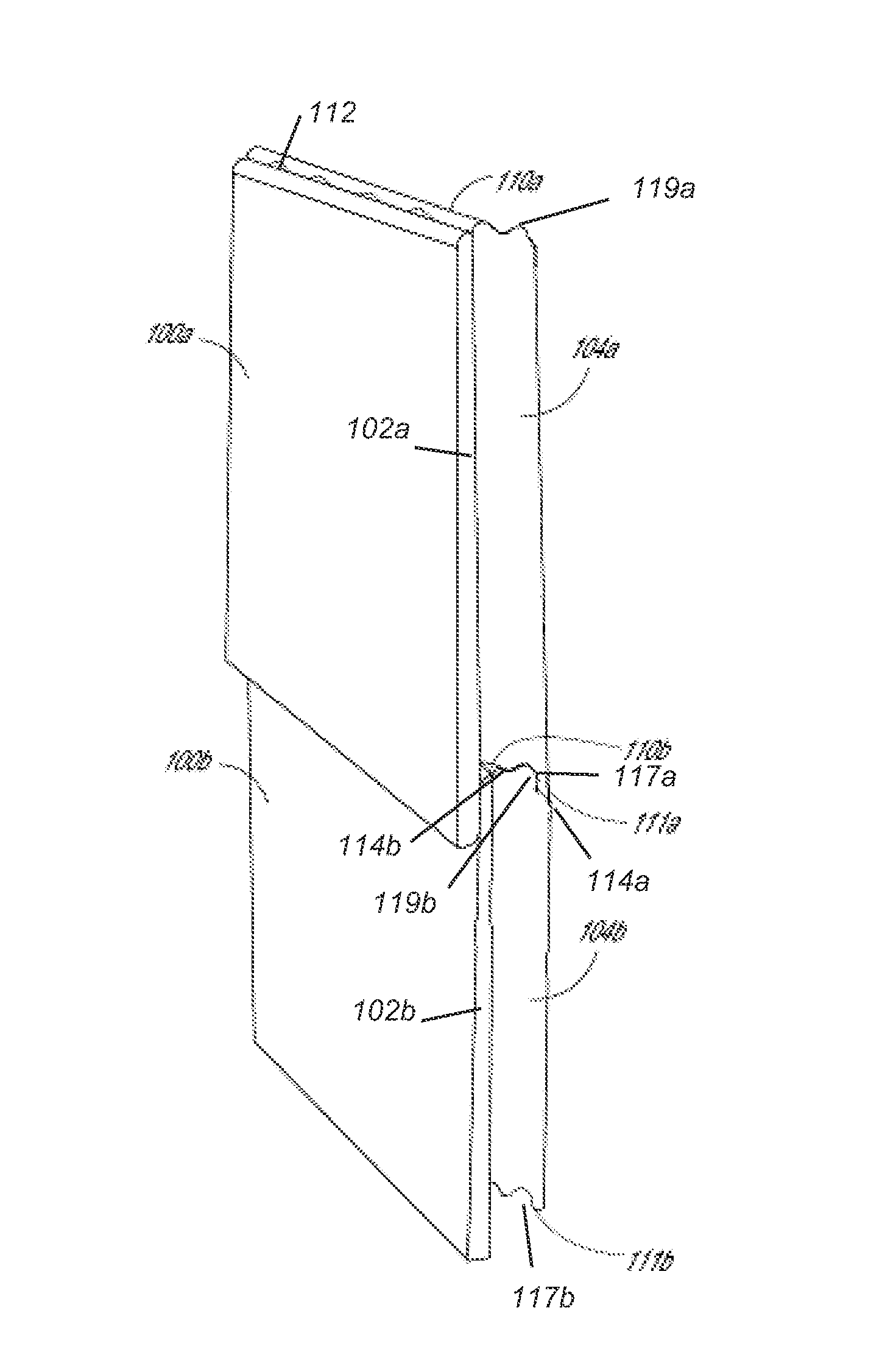
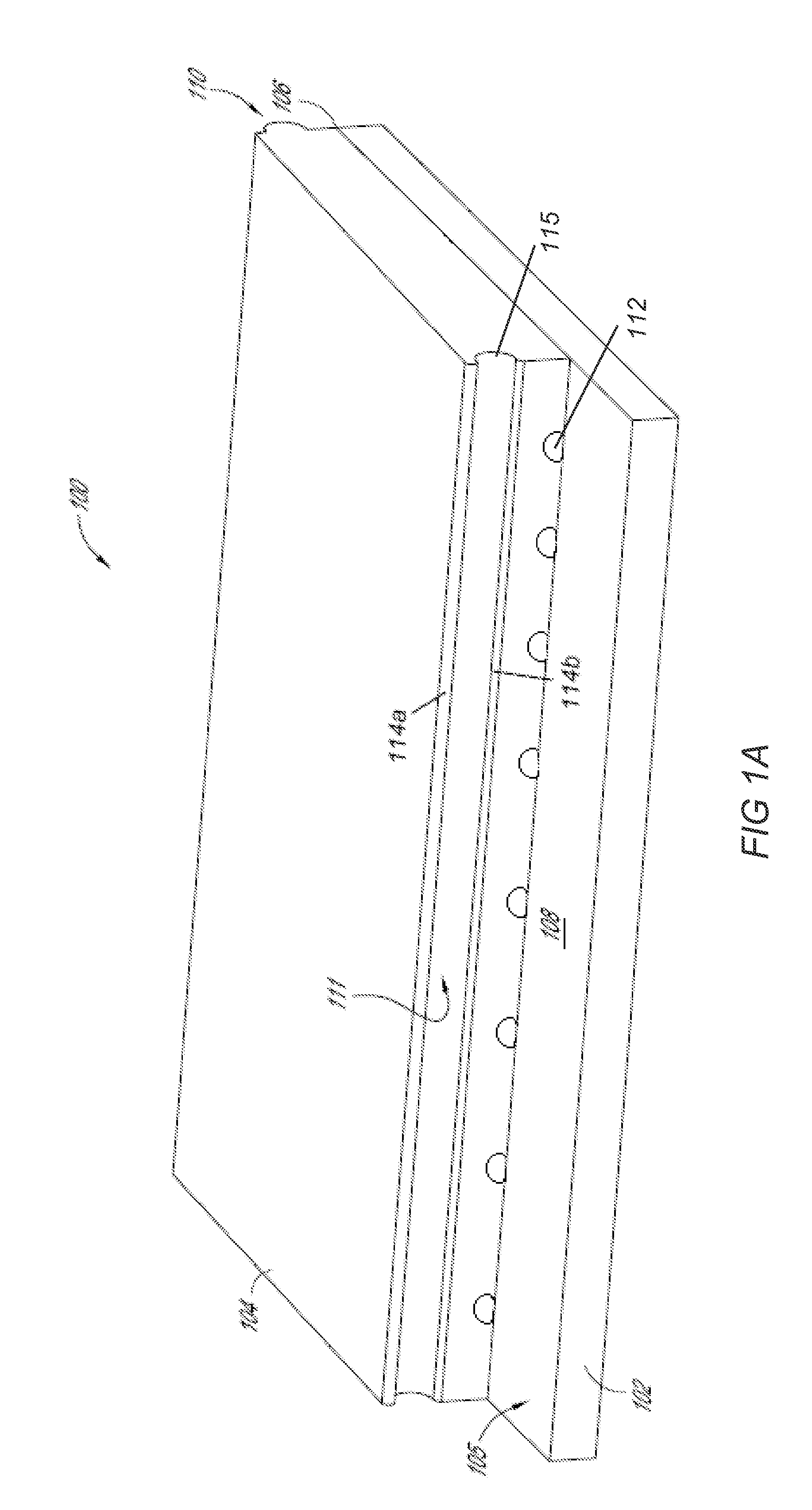
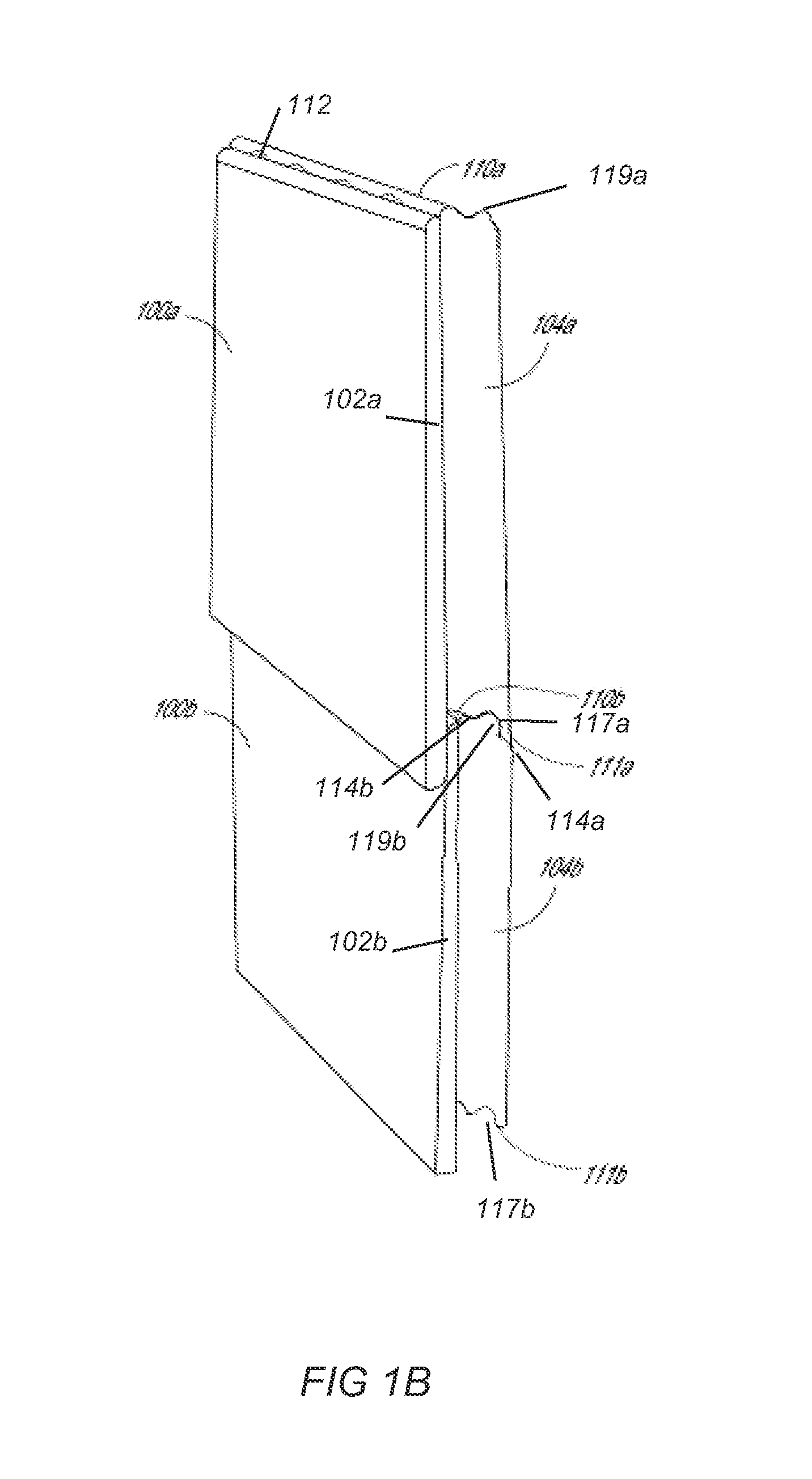
[0039]References will now be made to the drawings wherein like numerals refer to like parts throughout. FIG. 1A illustrates an integrated fiber cement and foam insulation panel 100 configured for exterior siding applications in accordance with various embodiments of the present disclosure. The panel 100 generally includes a fiber cement layer 102 and a profiled foam layer 104 attached thereto. The fiber cement layer 102 can be in the form of a plank, a siding, a shingle, a strip, a trim board, or various other building components. In a preferred embodiment, the fiber cement layer 102 is configured as a siding used for exterior wall applications. The profiled foam layer 104 can be made of open-celled and / or closed-celled foam or other similar lightweight material with insulating material properties, such as polystyrene foam, mineral based foams, foamed cement or gypsum, phenolic foams, and aerogels. Additionally or alternatively, the profiled foam layer 104 may also comprise mineral ...


PUM


Abstract

An integrated fiber cement and foam cladding system is provided that incorporates foam or similar light weight material to improve the insulation capacity of the cladding system. The system includes at least a fiber cement layer and a foam layer disposed on the backside of the fiber cement layer. The system improves the R-value of the building, a measure of the building's resistance to transferring heat or thermal energy.

Description

CROSS-REFERENCE TO RELATED APPLICATIONS[0001]This application claims the benefit of priority under 35 U.S.C. §119(e) of U.S. Provisional Application No. 61 / 619,872, filed on Apr. 3, 2012, the entirety of which is incorporated herein by reference.BACKGROUND OF THE INVENTION[0002]1. Field of the Invention[0003]The present disclosure generally relates to building construction materials and methods, and more particularly relates to composite fiber cement cladding with improved properties and methods of installing such material.[0004]2. Description of the Related Art[0005]The future of building construction is moving towards providing an insulated, energy efficient building envelope. In particular, there is an increasing demand for energy efficient residential and commercial constructions which require walls having greater building insulation ratings. The R-value of building insulation is a measure of its resistance to transferring heat or thermal energy. Greater R-values indicate more e...

Claims


Application Information

Patent Timeline
IPC IPC(8): E04C2/288E04F13/00E04C2/52E04C2/20E04C2/24E04B2/00E04B2/28E04F13/21
CPCE04C2/288E04B2/28E04F13/007E04F13/21E04C2002/004E04C2/243E04C2/246E04C2/46E04C2/52E04C2/205E04F13/148E04F13/0864E04F19/064E04F2201/0107E04F2203/04E04F2290/041E04F13/0878Y02A30/00Y02B30/90E04F13/0817E04F13/076E04F13/0894E04B1/7069E04B1/7645E04B2/707E04B1/765E04F13/0866E04F13/0869E04F13/141B32B3/06B32B3/085B32B3/30B32B5/18B32B5/32B32B13/045B32B2250/04B32B2266/0228B32B2307/102B32B2607/00E04B1/762E04F13/077
Inventor COLE, DAWNELIZARRARAS, GEORGELI, HUIO'LEARY, KEVINO'LEARY, SEAN
Owner JAMES HARDIE TECH LTD
Learn More