Syntax and semantics for adaptive loop filter and sample adaptive offset

Active Publication Date: 2015-01-15
SUN PATENT TRUST
View PDF8 Cites 25 Cited by
  • Summary
  • Abstract
  • Description
  • Claims
  • Application Information

AI Technical Summary

Benefits of technology

The present invention provides a way to improve video coding by using LCUs and reducing the signaling overhead. The coding scheme uses groups of LCUs to signal filter parameters, instead of a single LCU like in previous methods. This reduces the size of the signaling overhead. At the decoder side, the mapping function is applied to determine which LCU group a particular LCU belongs to, which preserves the advantages of LCU-based signaling syntax. Overall, the invention allows for greater flexibility and efficiency in video coding.

Problems solved by technology

Due to the block-wise coding, the superposed noise often has blocking characteristics, which result, in particular for strong quantization, in visible block boundaries in the decoded image.
Such blocking artifacts have a negative effect upon human visual perception.
However, compared to the LCU-based approach, the frame-based approach creates additional delay in the encoder and requires additional external memory access.
Since frame-based syntax is only applicable to frame-based filter parameter estimation, it creates an additional delay (frame-level encoding delay).
Therefore, frame-based syntax is not suitable for low-delay applications such as teleconferencing.
Further, the enhanced external memory access requirements in the encoder represent a drawback of frame-based syntax structures.
However, it is a drawback of LCU-based syntax that an LCU parameter unit must be transmitted (signaled) for each LCU.
Therefore, LCU-based syntax causes more parameter signaling overhead compared to the frame-based approach.
Due to the higher level of signaling overhead, the LCU-based syntax causes coding loss compared to the frame-based syntax, even in the case of frame-based estimation.

Method used


Image

  • Syntax and semantics for adaptive loop filter and sample adaptive offset
  • Syntax and semantics for adaptive loop filter and sample adaptive offset
  • Syntax and semantics for adaptive loop filter and sample adaptive offset

Examples


embodiment a

[0194]FIG. 16 illustrates an overall configuration of a content providing system ex100 for implementing content distribution services. The area for providing communication services is divided into cells of desired size, and base stations ex106, ex107, ex108, ex109, and ex110 which are fixed wireless stations are placed in each of the cells.

[0195]The content providing system ex100 is connected to devices, such as a computer ex111, a personal digital assistant (PDA) ex112, a camera ex113, a cellular phone ex114 and a game machine ex115, via the Internet ex101, an Internet service provider ex102, a telephone network ex104, as well as the base stations ex106 to ex110, respectively.

[0196]However, the configuration of the content providing system ex100 is not limited to the configuration shown in FIG. 16, and a combination in which any of the elements are connected is acceptable. In addition, each device may be directly connected to the telephone network ex104, rather than via the base st...

embodiment b

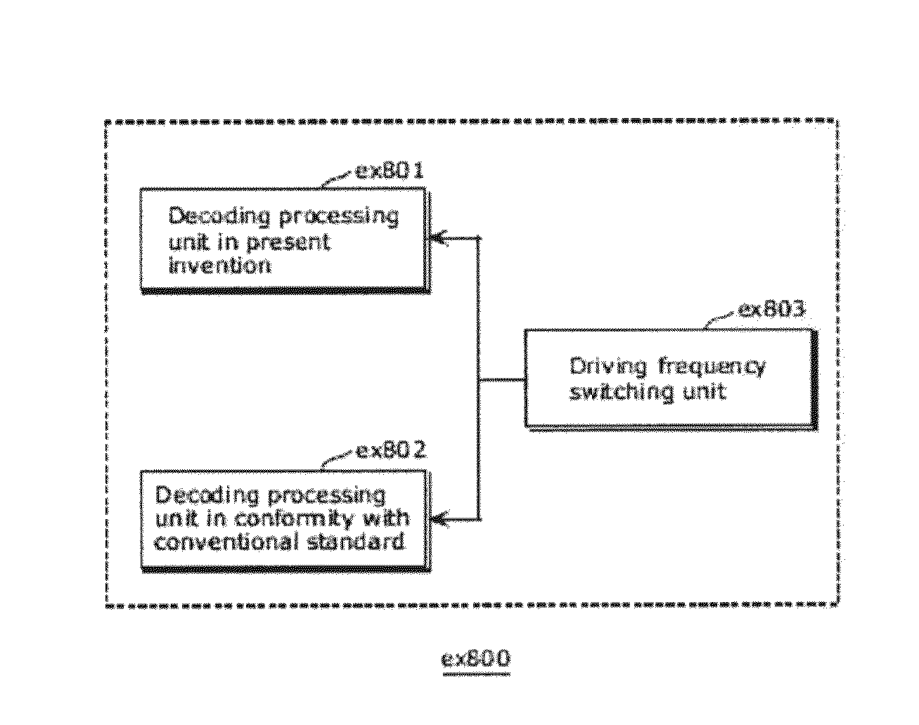
[0226]Video data can be generated by switching, as necessary, between (i) the moving picture coding method or the moving picture coding apparatus shown in each of embodiments and (ii) a moving picture coding method or a moving picture coding apparatus in conformity with a different standard, such as MPEG-2, MPEG-4 AVC, and VC-1.

[0227]Here, when a plurality of video data that conforms to the different standards is generated and is then decoded, the decoding methods need to be selected to conform to the different standards. However, since to which standard each of the plurality of the video data to be decoded conform cannot be detected, there is a problem that an appropriate decoding method cannot be selected.

[0228]In order to solve the problem, multiplexed data obtained by multiplexing audio data and others onto video data has a structure including identification information indicating to which standard the video data conforms. The specific structure of the multiplexed data including...

embodiment c

[0243]Each of the moving picture coding method, the moving picture coding apparatus, the moving picture decoding method, and the moving picture decoding apparatus in each of embodiments is typically achieved in the form of an integrated circuit or a Large Scale Integrated (LSI) circuit. As an example of the LSI, FIG. 30 illustrates a configuration of the LSI ex500 that is made into one chip. The LSI ex500 includes elements ex501, ex502, ex503, ex504, ex505, ex506, ex507, ex508, and ex509 to be described below, and the elements are connected to each other through a bus ex510. The power supply circuit unit ex505 is activated by supplying each of the elements with power when the power supply circuit unit ex505 is turned on.

[0244]For example, when coding is performed, the LSI ex500 receives an AV signal from a microphone ex117, a camera ex113, and others through an AV IO ex509 under control of a control unit ex501 including a CPU ex502, a memory controller ex503, a stream controller ex5...


PUM


Abstract

The present invention provides an improved video encoding and decoding method, which maintains the advantages of LCU-based filter parameter signaling as compared to frame-based filter parameter signaling, but considerably reduces signaling overhead. Therefore, signaling syntax is modified by grouping LCUs (Largest Coding Units) together for signaling employing a mapping function. Consequently, filter parameters no longer need to be signaled for each single LCU, but for a group of several LCUs. The syntax structure of the invention avoids redundancies present in the state of the art as far as possible and thus increases the information content of the syntax elements. At the decoder side, the mapping function is applied to infer information about the filter parameters to be applied to a current LCU from information encoded in different syntax structures.

Description

CROSS REFERENCE TO RELATED APPLICATIONS[0001]This application is a continuation of International Application No. PCT / EP2013 / 056401, filed Mar. 26, 2013, which claims the benefit of U.S. Provisional Patent Application No. 61 / 617,915, filed Mar. 30, 2012. The entire disclosures of the above-identified applications, including the specifications, drawings and claims are incorporated herein by reference in their entirety.BACKGROUND OF THE INVENTION[0002]1. Field of the Invention[0003]The present invention relates to the field of video image coding and decoding. In particular, the present invention relates to encoding / decoding employing filters with variable filter parameters.[0004]2. Description of the Related Art[0005]At present, the majority of standardized video coding algorithms are based on hybrid video coding. Hybrid video coding methods typically combine several different lossless and lossy compression schemes in order to achieve the desired compression gain. Hybrid video coding i...

Claims


Application Information

Patent Timeline
IPC IPC(8): H04N19/80H04N19/117H04N19/70
CPCH04N19/0089H04N19/00884H04N19/00066H04N19/117H04N19/463H04N19/174H04N19/70H04N19/80
Inventor ESENLIK, SEMIHNARROSCHKE, MATTHIASKAMP, STEFFENWEDI, THOMAS
Owner SUN PATENT TRUST
Why Eureka
Try Eureka