Signal separation apparatus

a signal separation and apparatus technology, applied in the direction of electrical apparatus, impedence networks, etc., can solve the problems of reducing degrading the characteristics, and achieve the reduction of the longitudinal dimension of the reception filter, the significant reduction of the size of the signal separation apparatus, and the significant increase of the degree of freedom in designing the transmission filter

Active Publication Date: 2015-11-24
MURATA MFG CO LTD
View PDF16 Cites 0 Cited by
  • Summary
  • Abstract
  • Description
  • Claims
  • Application Information

AI Technical Summary

Benefits of technology

[0007]Accordingly, preferred embodiments of the present invention provide a signal separation apparatus which includes a longitudinally coupled resonator-type elastic wave filter and which allows a longitudinal dimension to be significantly reduced and a degree of freedom in designing a transmission filter to be significantly increased.
[0015]Since the signal separation apparatus according to a preferred embodiment of the present invention includes the first, second and third longitudinally coupled resonator-type elastic wave filter devices in which the longitudinally coupled resonator-type elastic wave filter units are cascade-connected in two stages, that is, the reception filter having a two-stage six-element configuration is preferably used, the dimension of the reception filter in the longitudinal direction is significantly decreased. Further, since the transmission filter is arranged in a region extending from the reception filter in an interstage direction of the two-stage serial connection in the reception filter, the size of the signal separation apparatus is significantly reduced. Further, the degree of freedom in designing the transmission filter is significantly increased.

Problems solved by technology

In addition, there has been a problem in that the degree of freedom in designing a transmission filter is decreased.
On the other hand, when a reception filter formed of a longitudinally coupled resonator-type elastic wave filter and a transmission filter are arranged in the lateral direction described above, characteristics are degraded due to mutual influence caused by leakage of signals.

Method used


Image

  • Signal separation apparatus
  • Signal separation apparatus
  • Signal separation apparatus

Examples


Embodiment Construction

[0024]Hereinafter, specific preferred embodiments of the present invention will be described with reference to the drawings.

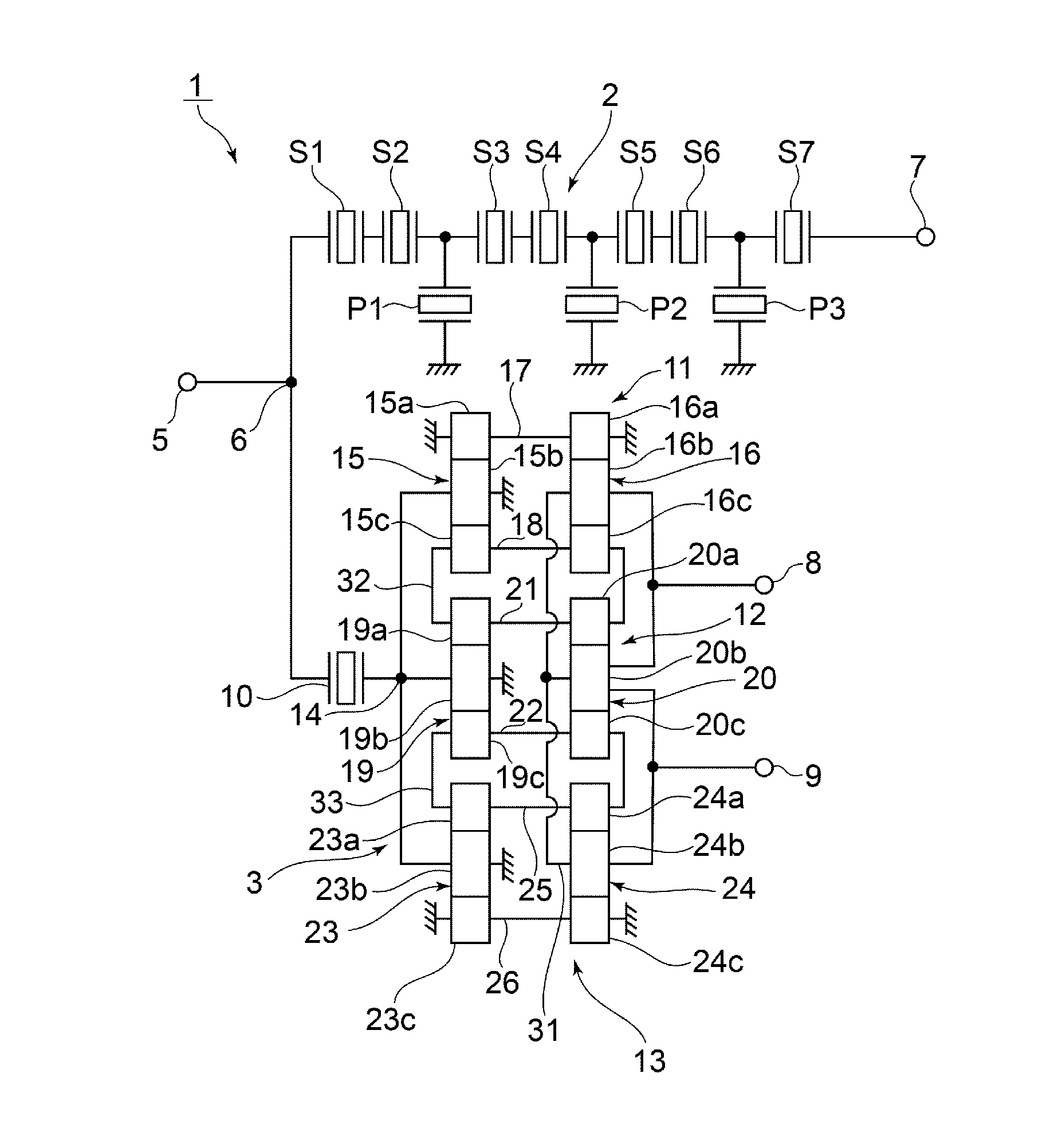
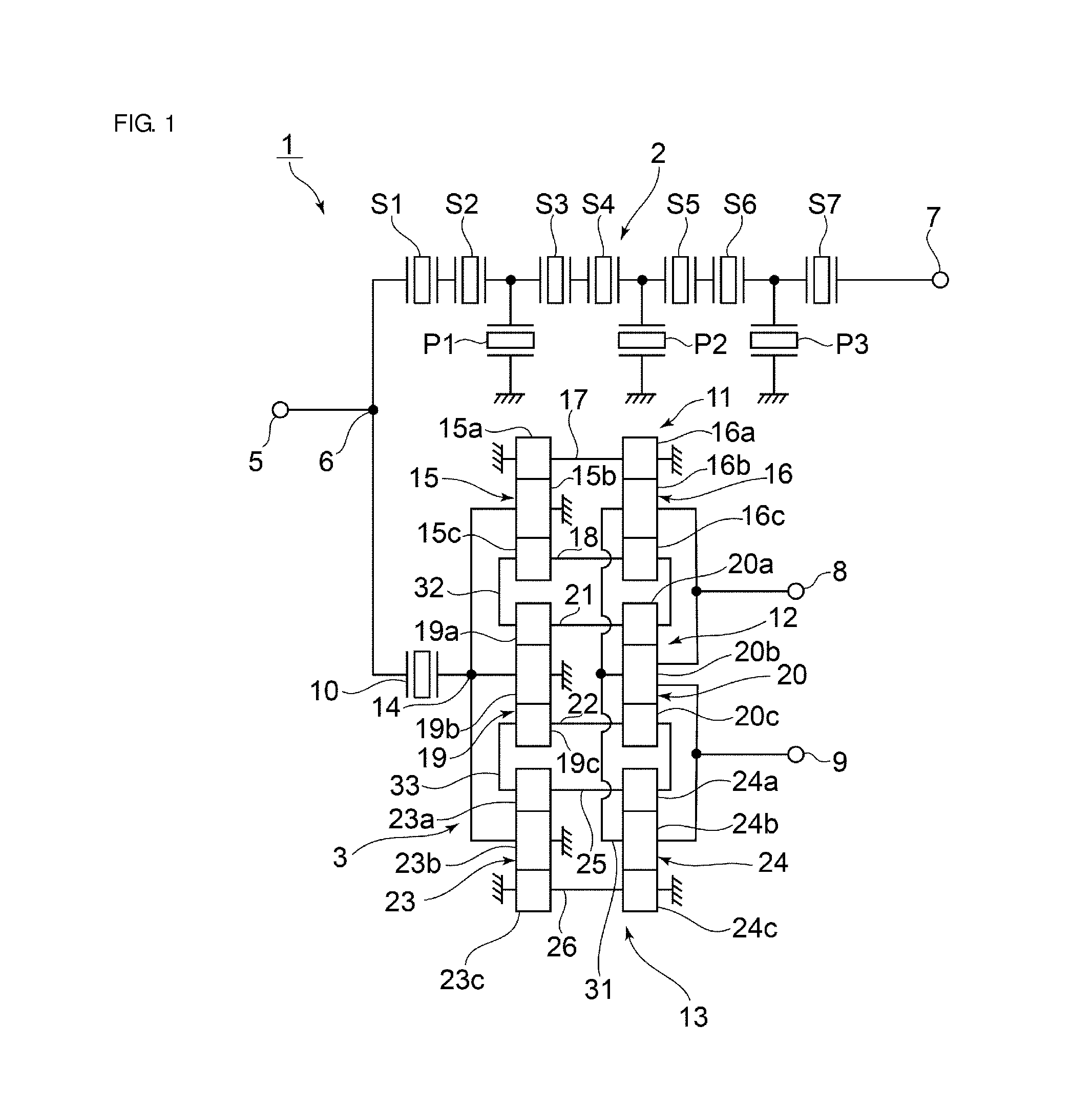
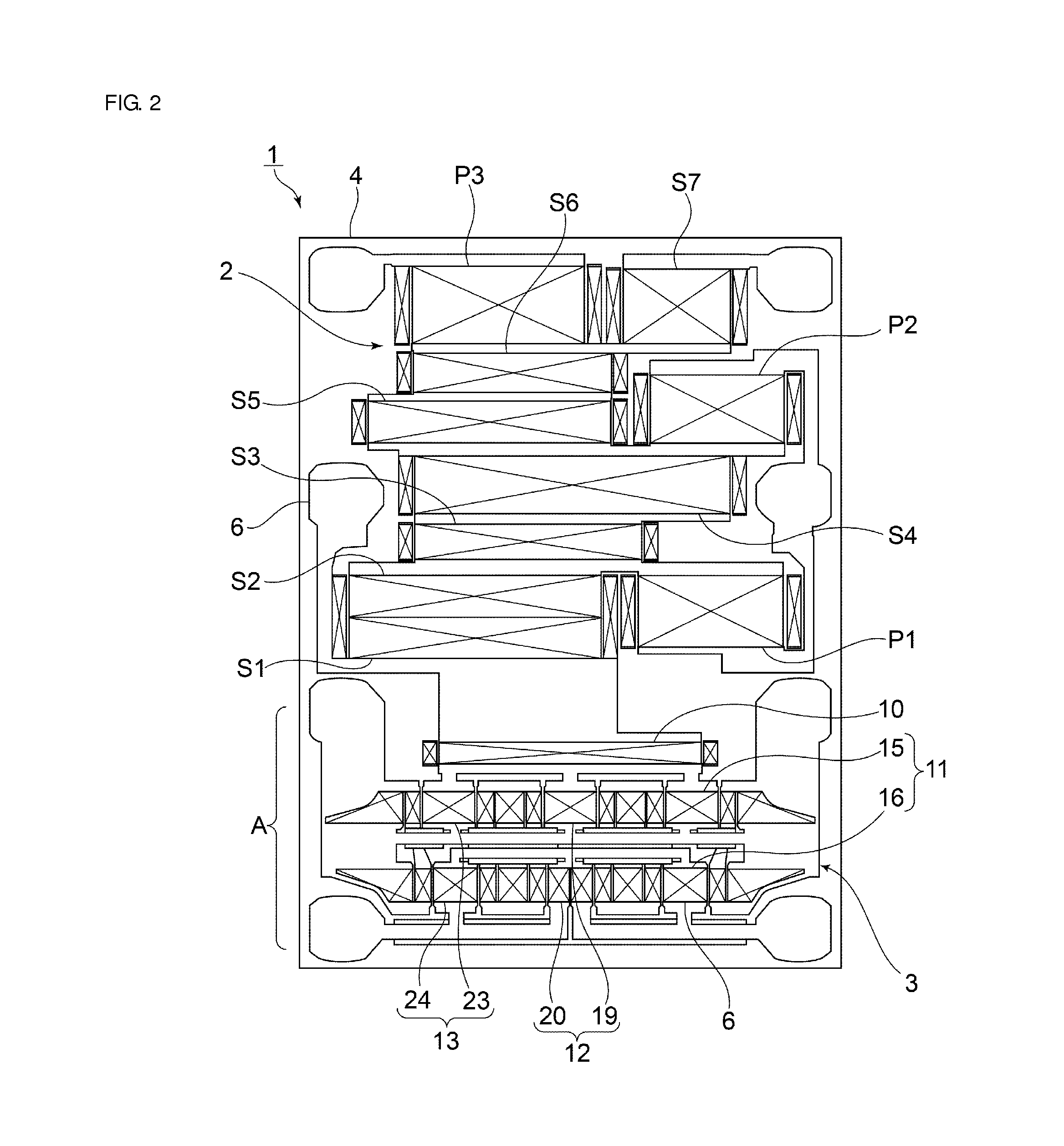
[0025]FIG. 1 is a circuit diagram of a duplexer according to a first preferred embodiment of the present invention, and FIG. 2 is a schematic plan view thereof.

[0026]Referring to FIG. 1, a signal separation apparatus 1 includes a transmission filter 2 and a reception filter 3. Referring to FIG. 2, in the signal separation apparatus 1, the transmission filter 2 and the reception filter 3 described above are provided on a piezoelectric substrate 4.

[0027]Referring back to FIG. 1, the signal separation apparatus 1 includes an antenna terminal 5 and a common connection point 6 connected to the antenna terminal 5. The transmission filter 2 is connected between the common connection point 6 and a transmission terminal 7. The reception filter 3 is connected between the common connection point 6 and first and second balanced terminals 8 and 9. In the present preferred e...


PUM


Abstract

A signal separation apparatus includes a piezoelectric substrate on which a transmission filter and a reception filter are provided. The reception filter includes first, second and third longitudinally coupled resonator-type elastic wave filter devices and the first, second and third longitudinally coupled resonator-type elastic wave filter devices each including a two-stage cascade connection structure. The signal separation apparatus further includes virtual ground wiring lines that are not connected to a ground potential and that connect ground terminals of adjacent longitudinally coupled resonator-type elastic wave filter units to each other on at least one of a first, second, and third group-A longitudinally coupled resonator-type elastic wave filter units side and a first, second, and third group-B longitudinally coupled resonator-type elastic wave filter units side.

Description

BACKGROUND OF THE INVENTION[0001]1. Field of the Invention[0002]The present invention relates to a signal separation apparatus including a longitudinally coupled resonator-type elastic wave filter apparatus that includes a plurality of longitudinally coupled resonator-type elastic wave filter devices having a two-stage cascade connection structure.[0003]2. Description of the Related Art[0004]A duplexer, which is a type of signal separation apparatus, used for mobile communication includes a transmission filter and a reception filter. To date, longitudinally coupled resonator-type elastic wave filter apparatuses have been widely used as reception filters. In Japanese Unexamined Patent Application Publication No. 2012-205215, a longitudinally coupled resonator-type elastic wave filter apparatus used as a reception filter includes first and second longitudinally coupled resonator-type elastic wave filter devices. In each of the first and second longitudinally coupled resonator-type ela...

Claims


Application Information

Patent Timeline
Patent Type & Authority Patents(United States)
IPC IPC(8): H03H9/60H03H9/72H03H9/64H03H9/00
CPCH03H9/725H03H9/0057H03H9/6456
Inventor TAKAMINE, YUICHI
Owner MURATA MFG CO LTD
Why Eureka
Try Eureka