
Piezoelectric device and method for fabricating the same

Inactive Publication Date: 2015-01-15
NIHON DEMPA KOGYO CO LTD
View PDF4 Cites 17 Cited by
  • Summary
  • Abstract
  • Description
  • Claims
  • Application Information

AI Technical Summary

Benefits of technology

The patent text describes a method of coating an excitation electrode with a metal cover to protect it when plasma or ion beam is used for activation bonding. However, this method is expensive and may affect the vibration characteristic of the piezoelectric vibrating piece. The technical effect of the patent text is to provide a simpler and more cost-effective method of coating the excitation electrode without affecting the vibration characteristic of the piezoelectric vibrating piece.

Problems solved by technology

However, growing market demands for reduction in size, profile, and price of electronic components make it difficult to use a ceramic package.
The direct wafer bonding method requires high temperature heat treatment for obtaining sufficient bonding strength, which is problematic for a bonding method of a crystal unit.
The thermo-compression metal bonding method is bonding method for bonding via a metal such as AuSn eutectic metal, and thus requires the formation of an adhesive layer or a barrier layer, and patterning them, which disadvantageously increases fabrication cost.
The glass frit bonding method generates gases from a low melting point glass paste during bonding, which deteriorates degree of vacuum in a package.
The plasma activation bonding method is considered to be difficult for bonding in vacuum.
In the fabrication of a crystal unit, such a frequency variation caused after bonding of the wafers unfortunately decreases product yield.
It is, however, cumbersome to coat the excitation electrode of each piezoelectric vibrating piece with the electrode in wafer level, and increases production cost.
In addition, since the electrode cover is also etched by an ion beam or a similar beam, the deposition of the metal elements may affect the vibration characteristic of the piezoelectric vibrating piece.

Method used


Image

  • Piezoelectric device and method for fabricating the same
  • Piezoelectric device and method for fabricating the same
  • Piezoelectric device and method for fabricating the same

Examples


second embodiment

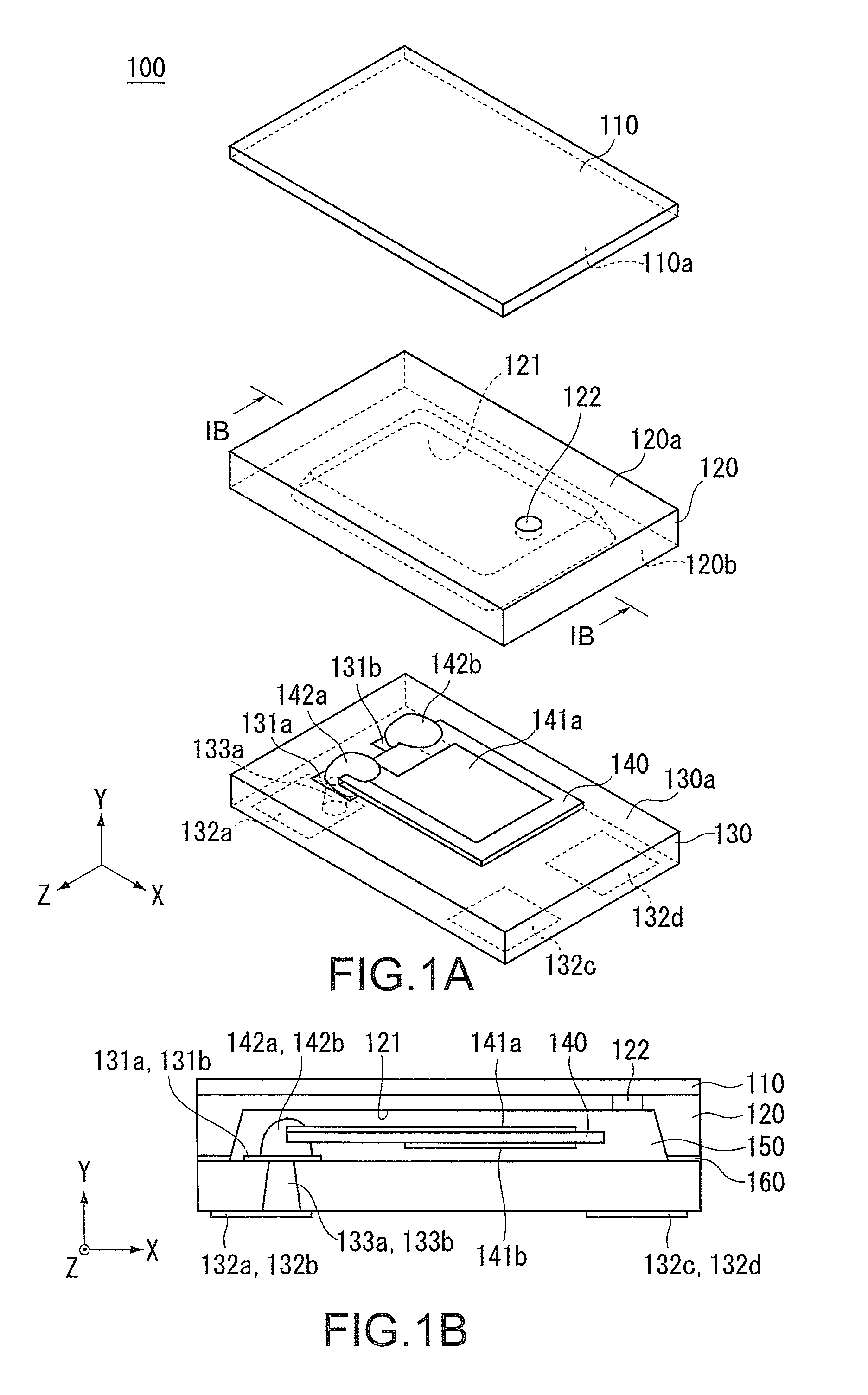
[0060]The following description describes the second embodiment. In the following description, a component that is identical or equal to that of the first embodiment is indicated by the same reference numeral, and the description thereof is omitted or simplified. FIG. 5 illustrates a piezoelectric device 200 according to the second embodiment. In particular, FIG. 5 is a cross-sectional view taken along the line corresponding to the line IB-IB of FIGS. 1A and 1B. Similarly to the first embodiment, the piezoelectric device 200 includes the piezoelectric vibrating piece 140.

[0061]As illustrated in FIG. 5, the piezoelectric device 200 is a piezoelectric resonator that includes a second lid 210, a first lid 220, a base 230, and the piezoelectric vibrating piece 140. The base 230, on which the piezoelectric vibrating piece 140 is placed, is bonded to the first lid 220, for example, via a seal 260 made of a low melting point glass, further the first lid 220 is bonded to the second lid 210 ...


PUM

PropertyMeasurementUnit
Shapeaaaaaaaaaa

Abstract

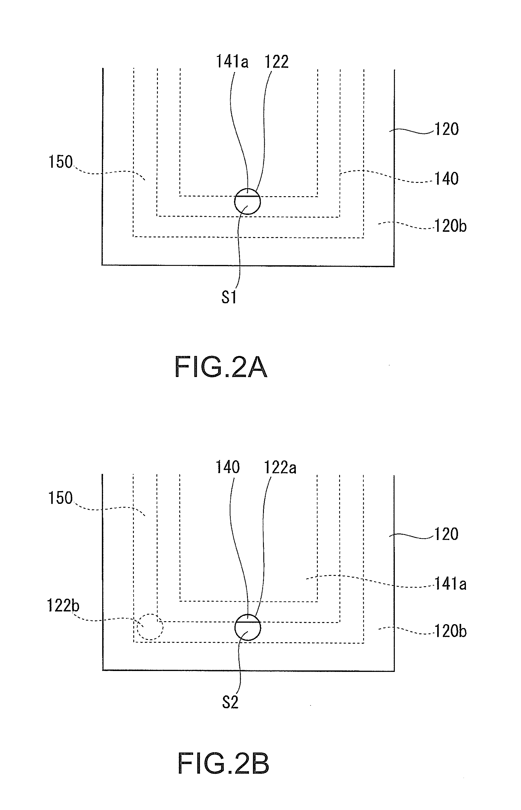
A piezoelectric device includes a piezoelectric vibrating piece, a base, a first lid, and a second lid. The piezoelectric vibrating piece includes an electrode. The base holds the piezoelectric vibrating piece. The first lid is bonded to the base. The first lid houses the piezoelectric vibrating piece in a cavity. The first lid has an opening portion that opens the cavity. The second lid is bonded to a front surface of the first lid so as to cover the opening portion. The opening portion is fabricated at a position overlapping a portion including a region of the piezoelectric vibrating piece excluding the electrode, or a portion including a region excluding the piezoelectric vibrating piece in plan view.

Description

CROSS-REFERENCE TO RELATED APPLICATIONS[0001]This application claims the priority benefit of Japan application serial no. 2013-143496, filed on Jul. 9, 2013. The entirety of the above-mentioned patent application is hereby incorporated by reference herein and made a part of this specification.TECHNICAL FIELD[0002]This disclosure relates to a piezoelectric device and a method for fabricating the piezoelectric device.DESCRIPTION OF THE RELATED ART[0003]A piezoelectric resonator (piezoelectric device) such as a crystal unit is fabricated by placing a quartz crystal piece (piezoelectric vibrating piece) in a package made of a ceramic or similar material, then hermetically sealing or vacuum-sealing the package. However, growing market demands for reduction in size, profile, and price of electronic components make it difficult to use a ceramic package. In order to meet these demands, piezoelectric resonators using a glass package have been proposed (for example, see Japanese Unexamined Pa...

Claims


Application Information

Patent Timeline
IPC IPC(8): H01L41/053H01L41/23
CPCH01L41/053H01L41/23Y10T29/42H03H9/1021H03H2003/022H03H2003/0428
Inventor KAMIJO, ATSUSHI
Owner NIHON DEMPA KOGYO CO LTD
Learn More