
Air heat exchanger

a heat exchanger and air technology, applied in the field of heat exchangers, can solve the problems of high power consumption of fans, low heat exchange efficiency of heat exchangers,

Inactive Publication Date: 2014-12-18
LU CHENFEI
View PDF18 Cites 15 Cited by
  • Summary
  • Abstract
  • Description
  • Claims
  • Application Information

AI Technical Summary

Benefits of technology

The invention is a new type of air heat exchanger that is designed to be more efficient and to reduce the noise and power consumption of the fan. It can be used in a variety of heat exchange situations and is easy to install in mobile vehicles. Overall, the invention provides a more efficient and effective air heat exchanger.

Problems solved by technology

Compared with the novel heat exchanger, heat exchangers of the prior art have many disadvantages, for example, a low heat exchange efficiency, a high power consumption of the fan, and loud blowing noise.
Heat exchangers of the prior art cannot be too high or too large in size because they are restricted by the layout of the main equipment.
In these solutions, air flows back into the atmosphere at a high speed, which causes a waste of kinetic energy.
In addition, the efficiency of the fans is not high.
The noise of the fans is very loud, however.
The number of vehicles and small refrigerating air conditioners demanded in society is very large.

Method used


Image

  • Air heat exchanger
  • Air heat exchanger
  • Air heat exchanger

Examples


embodiment 1

[0034

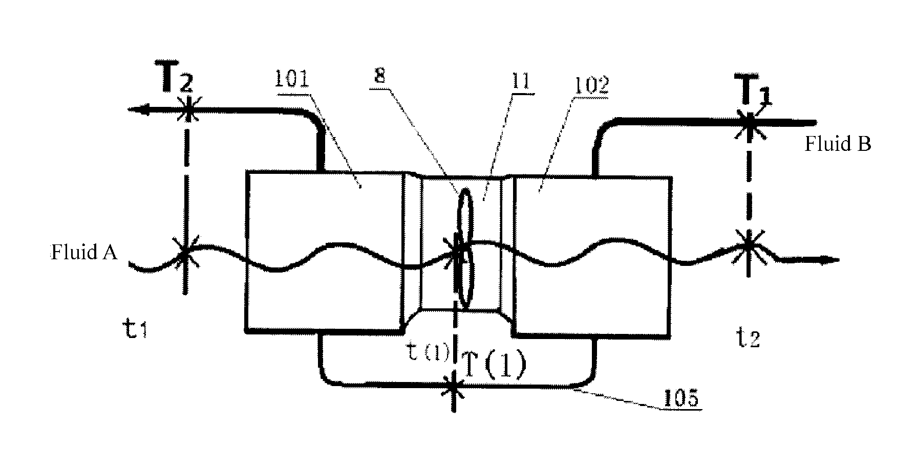
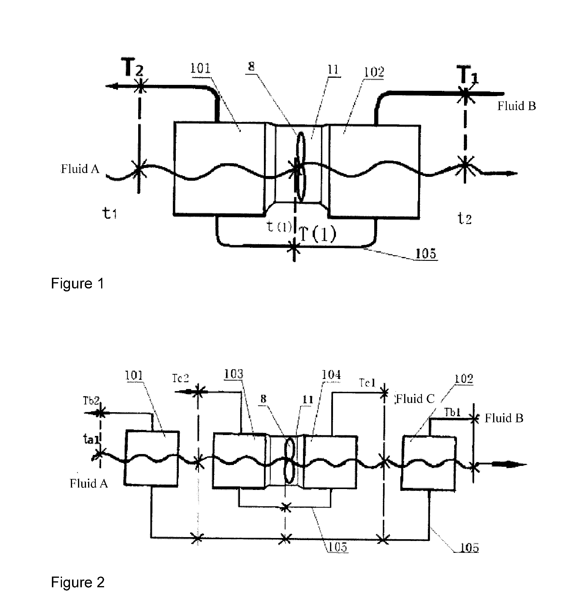
[0035]See FIG. 1, which shows a high-efficiency air heat exchanger comprising a heat exchange subunit 1 (101), a fan 8, an air duct 11, a heat exchange subunit connecting pipe 105, and a heat exchange subunit 2 (102). Heat exchange subunit 1 (101), heat exchange subunit 2 (102), heat exchange subunit 3 (103), and heat exchange subunit 4 (104) in FIG. 1 and FIG. 2 are all horizontally vertical-cross-flow air heat exchangers, which can be air-cooled radiators, air-to-air intercoolers, air condensers, or air evaporators. Heat exchange subunit 1 (101) and heat exchange subunit 2 (102) are connected in series with the heat exchange subunit connecting pipe 105. Owing to the negative pressure difference caused by rotations of the fan 8, cooling fluid A (cooling air) with a temperature of t1 enters heat exchange subunit 1 (101) to exchange heat with fluid B in heat exchange subunit 1 (101). After exchanging heat, cooling fluid A (cooling air) passing transversely enters the air duct 11...

embodiment 2

iency Air Radiator System for Internal Combustion Engines of Vehicles Shown in FIG. 3 and FIG. 4

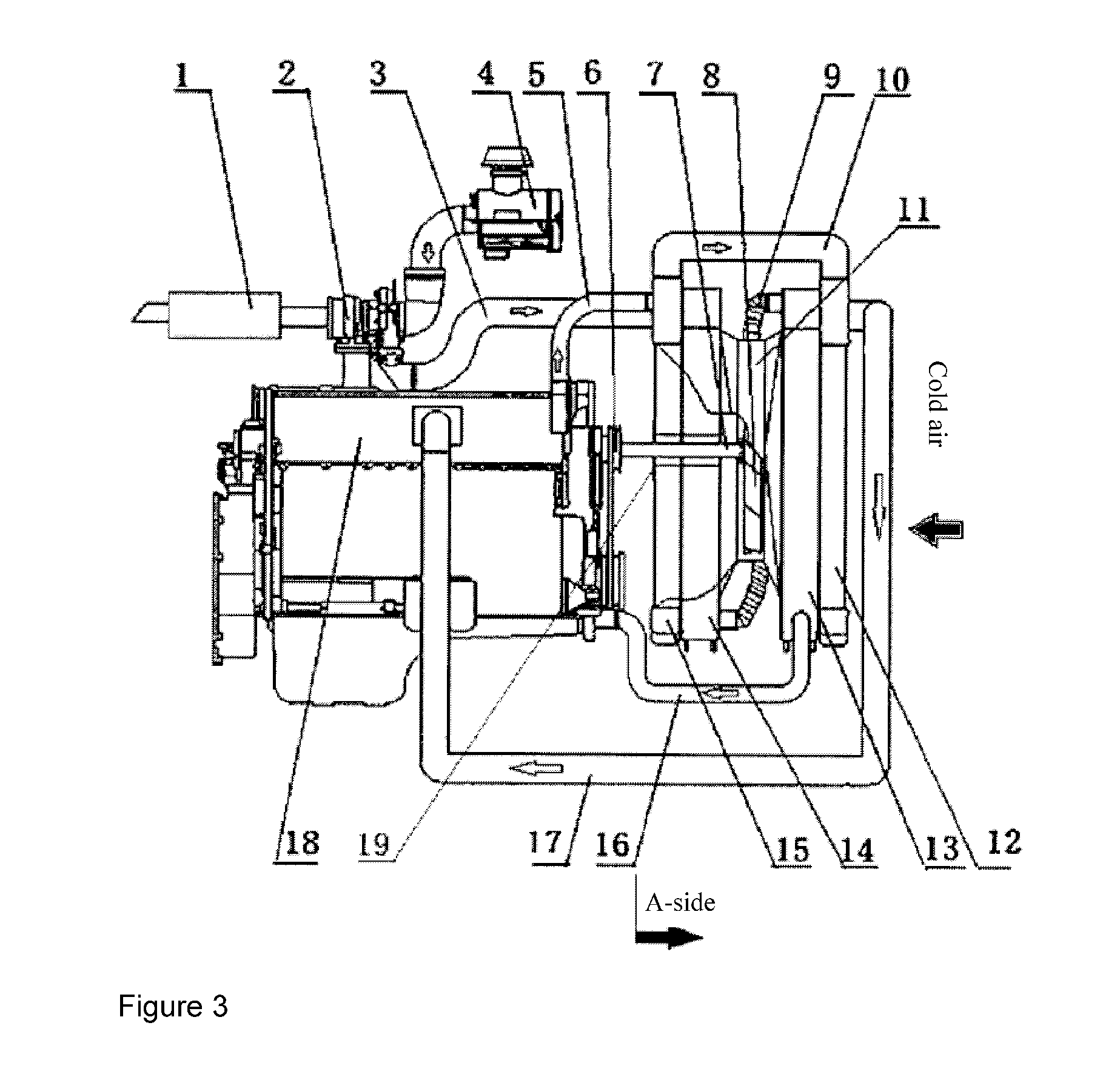
[0041]The high-efficiency air heat exchanger comprises an exhaust muffler 1 of the internal combustion engine, an exhaust-driven turbocharger 2, an air outlet pipe 3 of a compressor, an air filter 4, an outlet pipe 5 for cooled water of the internal combustion engine, a pulley 6 of the fan, a drive shaft 7 of the fan, a fan 8, a water-radiator connecting pipe 9, an intercooler connecting pipe 10, an air duct 11, a front air-to-air intercooler 12, a front radiator 13, a rear radiator 14, a rear air-to-air intercooler 15, a water inlet pipe 16 of a pump of the internal combustion engine, an air inlet pipe 17 of the internal combustion engine, an internal combustion engine 18, and gas-sealing discs 19. The internal combustion engine 18, the front radiator 13, the rear radiator 14, the exhaust muffler 1, and the air filter 4 are all connected to the chassis or support of the equipment. The fr...

embodiment 3

iency Air Heat Exchanger Assembly Applied in General Machinery, as Shown in FIG. 5

[0059]See FIG. 5 for the structural diagram. The electric motor 20, connected to the drive shaft 7 of the fan via the coupler 21 by means of bolts, transmits the torque to the fan 8. The blades of the fan 8 rotate in the air duct 11 to produce a positive pressure and a negative pressure in front of and behind the fan 8, respectively. Under the action of the negative pressure, the cooling air passes through the rear radiator 14 to enter the air duct 11. The air is driven by the fan 8 from left to right in FIG. 5 to enter the front radiator 13. After exchanging heat with hot fluid A in the rear radiator 14 and the front radiator 13 in turn, the hot air goes into the atmosphere on the right side. The fan 8 in FIG. 5 is a blowing fan.

[0060]Hot fluid A goes from the circulation system of the main equipment to the front radiator 13 to exchange heat with the cold air passing transversely, and then enters the ...


PUM


Abstract

An air heat exchanger comprising a front-end heat exchanger (101), a fan (8), a ventilating duct (11), a back-end heat exchanger (102), a fan power source (20) and a fan drive shaft (7), wherein the front-end heat exchanger (101) and the back-end heat exchanger(102) are connected in series by a heat exchanger connecting tube (105); the front-end heat exchanger (101) and the back-end heat exchanger (102) can each consist of one or more overlaid heat exchange units, respectively arranged upstream and downstream of a fan channel; the fan (8) is set up inside the ventilating duct (11) of the heat exchanger, adopting two-process cross-flow and counterflow heat exchange. The air heat exchanger features a simple structure, mature technology, high heat exchange efficiency, a compact structure and a fan with low power consumption and a low noise level, and of low cost.

Description

FIELD OF THE INVENTION[0001]The invention relates to a heat exchanger, in particular a high-efficiency air heat exchanger used in electromechanical devices such as construction machinery, mobile vehicles, refrigerators, internal combustion engines, transformers, and large machine tools.PRIOR ART[0002]A heat exchanger using air and other fluids as cooling media is an indispensable device in construction machinery, mobile vehicles, internal combustion engines, small refrigerating machinery, and transformers. For example, the coolant radiator, intercooler, hydraulic oil radiator, and exhaust gas recirculation (EGR) cooler in a mobile vehicle driven by a water-cooled internal combustion engine, the forced air-cooled refrigerant condenser in small refrigerating machinery, and the air-cooled oil radiator in a large transformer all need to utilize a fan to force air to pass through the core of the cross-flow radiator transversely for heat exchange so that the heat from the cooled fluid in ...

Claims


Application Information

Patent Timeline
IPC IPC(8): F28D1/02F25D17/06F01P3/18F28F13/12
CPCF28D1/024F01P3/18F25D17/06F28F13/12B60K11/04F01P5/06F24F1/00F28D1/0435F28D1/0461F28D2001/028F28D2021/004F28D2021/0091F28F2250/08F02B29/0412F01P5/02F01P7/165F01P11/10F01P2003/182F01P2060/02
Inventor LU, CHENFEI
Owner LU CHENFEI
Learn More