Measuring Method Using a Measuring Apparatus for Cable Diagnosis and/or Cable Testing

Inactive Publication Date: 2014-11-27
HAGENUK KMT KABELMESSTECHN
View PDF4 Cites 10 Cited by
  • Summary
  • Abstract
  • Description
  • Claims
  • Application Information

AI Technical Summary

Benefits of technology

The invention provides a measuring apparatus and method for testing and diagnosing cables using a single signal application. The apparatus uses a damped diagnostic signal for a gentle and protective measuring method. An alternating voltage signal train is used to avoid unnecessary loading of the cable and allow for a gentle bipolar oscillating ramp-up or increase of the voltage up to the test voltage. The use of a low frequency test signal over a prescribed test period makes it possible to measure, evaluate, and recognize thermal effects in the test cable. The test signal can rise continuously and smoothly or in a stepped manner. The apparatus can sequentially carry out several cable test procedures and diagnostic procedures without any loss or waste of time, minimizing measurement errors. The diagnostic signal is preferably continuous and smoothly adjoins the test signal, avoiding voltage jumps and peaks and reducing the risk of damaging the cable during the transition. The apparatus includes an electronic switching element, such as a thyristor, which allows for a compact low-wear construction and short switching times.

Problems solved by technology

That generally has caused significant effort and expense due to the need for several different pieces of equipment, and due to the additional time for personnel to connect the different devices and carry out the distinct procedures.
As a result, especially for very long cables, this necessarily (as a limitation of the system) leads to a very long duration of the DC voltage loading, for example up to several minutes, which is not acceptable.
Such a conventional procedure can damage the cable, for example due to polarization effects, that is to say space charge formation.
Moreover, the cable testing and the cable diagnosis cannot be carried out by means of a single method, but rather several separate distinct measuring apparatuses are necessary for carrying out separate distinct measuring processes.

Method used


Image

  • Measuring Method Using a Measuring Apparatus for Cable Diagnosis and/or Cable Testing
  • Measuring Method Using a Measuring Apparatus for Cable Diagnosis and/or Cable Testing

Examples


Embodiment Construction

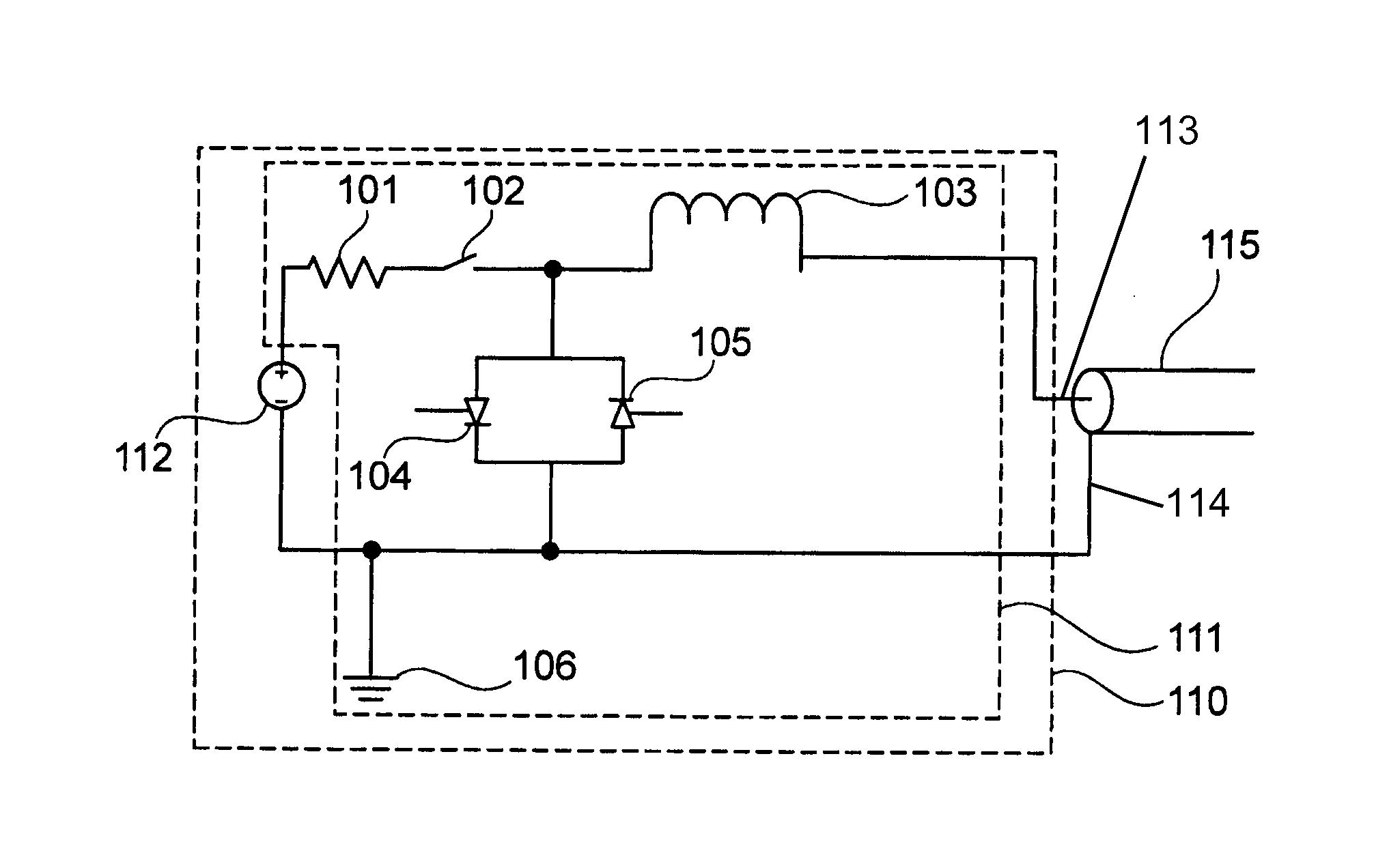
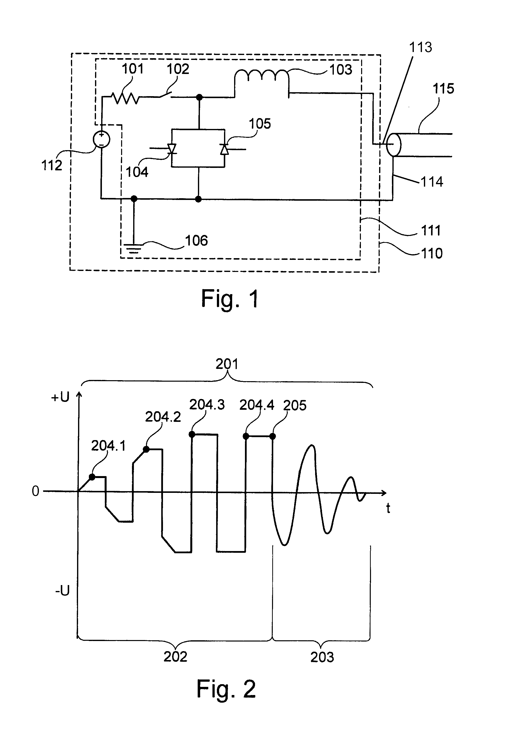
[0041]The measuring system schematically illustrated in FIG. 1 includes a measuring apparatus 110 and a test object represented schematically by a cable 115. The measuring apparatus 110 includes an electric energy source 112, such as a direct or DC voltage source, and a signal application device 111.

[0042]The signal application device 111 comprises an electrical resistor or resistance 101 circuit-connected to the electrical energy source 112 and in series with a switch 102, as well as a choke coil or inductor or inductance 103 connected in series between the switch 102 and a first test lead 113, which connects the device 111 with an inner central conductor of the cable 115. It should be understood that the resistor or resistance can be a single resistor component, or a plurality of resistor components, or any individual component or arrangement of plural components that provides the required total resistance value. Similarly, the inductor or inductance can be a single inductor compo...


PUM


Abstract

A measuring apparatus is connected to a cable to perform testing and diagnosis of the cable. The measuring apparatus includes a voltage source, a resistance, a switch, and an inductance forming a charging circuit, and two anti-parallel thyristors or switched diodes together with the inductance forming a series resonant circuit loop. The apparatus produces a low frequency alternating voltage signal train including a low frequency test signal followed by a low frequency diagnostic signal. The diagnostic signal is a damped decaying signal oscillation in the resonant circuit connected to the test cable. At least one of the signals is bipolar. Both cable testing and cable diagnosis can be performed using the same single measuring apparatus in a single measuring procedure.

Description

PRIORITY CLAIM[0001]This application is based on and claims the priority under 35 USC 119 of German Patent Application 10 2013 008 968.9, filed on May 22, 2013, the entire disclosure of which is incorporated herein by reference.FIELD OF THE INVENTION[0002]The invention relates to a measuring method using a measuring apparatus for performing cable diagnosis and / or cable testing of an electrical cable, by applying to the cable a low frequency alternating voltage signal train comprising a diagnostic signal and / or a test signal.BACKGROUND INFORMATION[0003]It is important to determine the electrical characteristics of an electrical cable, such as a medium voltage power distribution cable, in order to be able to ensure the fault-free and interference-free operation of a network having a cable system including the cable at issue. On the one hand, the cable can be subjected to so-called cable testing, in which the cable is tested for functionality, e.g. by determining any existing damage of...

Claims


Application Information

Patent Timeline
IPC IPC(8): G01R31/08
CPCG01R31/08G01R31/1272G01R31/14
Inventor SCHEUSCHNER, SVENBERTH, TORSTENPETZOLD, FRANK
Owner HAGENUK KMT KABELMESSTECHN
Why Eureka
Try Eureka