Aircraft electrical system

a technology of electrical system and airframe, applied in the direction of machines/engines, electric devices, machines/engines, etc., can solve the problems of not providing redundancy, unable to provide electrical power to the main engine, and unable to transfer power, so as to reduce the required power rating of the bidirectional converter, reduce the start time, and reduce the tonnage required for each starter generator to start the engin

Active Publication Date: 2014-11-13
ROLLS ROYCE PLC
View PDF6 Cites 50 Cited by
  • Summary
  • Abstract
  • Description
  • Claims
  • Application Information

AI Technical Summary

Benefits of technology

The invention concerns an aircraft electrical network that enables the first starter generator to be powered in starting mode using AC power from the DC bus, which may be provided by the APU or main engine. This eliminates the need for an additional AC interconnector, reducing weight. Additionally, the invention includes a further starter generator that can be operated in both starting and generating modes. By sequentially operating the two generators, the torque required for starting the engine is reduced, which in turn decreases the power rating of the converter and reduces start times.

Problems solved by technology

This method of providing electrical power to the main engines 26 also does not provide any redundancy, since if the interconnector 36 is not available, no power can be transferred to the starter generators 26.
Where the main engine starter generator 26 is powered by the APU 8, there is necessarily a delay while the APU 8 is started, which may be unacceptable.
During these periods, it may be necessary to open bleed valves (not shown) in order to prevent stall or surge of the compressor 14, which results in low fuel efficiency (i.e. higher fuel burn).

Method used


Image

  • Aircraft electrical system
  • Aircraft electrical system
  • Aircraft electrical system

Examples


Embodiment Construction

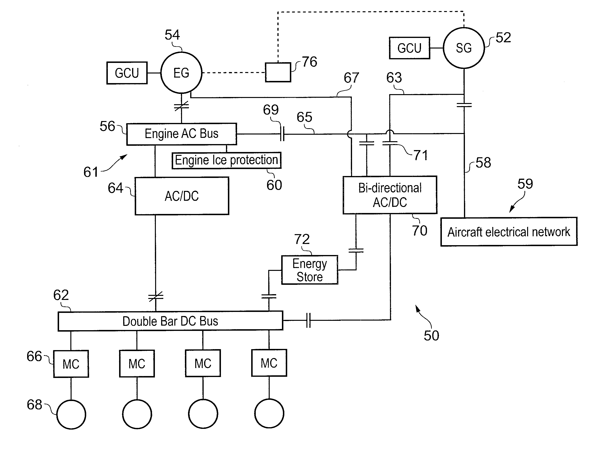
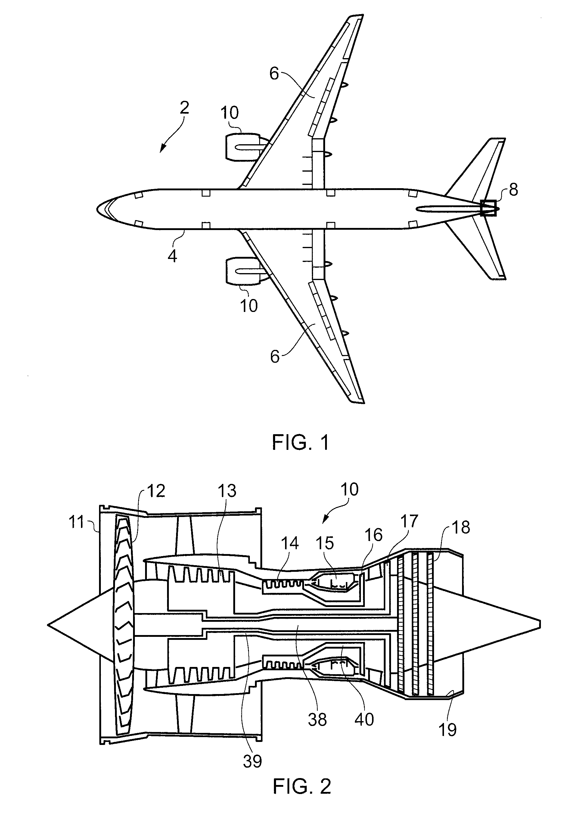
[0036]FIG. 4 shows an engine electrical network 50. The electrical network 50 comprises a first starter generator 52, and a further starter generator 54. Both starter generators 52 and 54 comprise multi-phase (preferably between 4 and 9 phases) AC electrical machines configured to provide AC electrical power when turned (i.e. when in a generating mode), and to provide motive power when provided with AC electrical power (i.e. when in a starting mode). The generators 52, 54 could for example comprise permanent magnet AC electrical generators, or wound field machines, or switched reluctance machines, or machines having a controllable AC field, such as doubly fed induction machines. The engine electrical network is part of an aircraft 2 (shown in FIG. 1), which comprises a fuselage 4 and a pair of wings 6. The aircraft includes a pair of wing mounted main engines 10, and an APU 8 mounted at the rear of the aircraft 2, within the empennage. An engine electrical network 50 is provided for...


PUM


Abstract

An aircraft electrical network including a first starter generator mechanically coupled to a first shaft of an aircraft main engine. The first starter generator is configured to turn the first shaft of the main engine in a starting mode, and to generate electricity from the first shaft of the gas turbine engine in a generating mode. The network further includes a DC electrical bus electrical coupled to one or more electrical loads and an AC electrical bus electrically coupled to the first starter generator. The DC electrical bus is electrically coupled to the AC electrical bus via a bi-directional AC / DC converter, which is configured to provide AC electrical power from the DC electrical bus to power the first starter generator when the first starter generator is in a starting mode, and DC electrical power to the DC electrical bus when the first starter generator is in a generating mode.

Description

FIELD OF THE INVENTION[0001]The present invention relates to an aircraft electrical system.BACKGROUND TO THE INVENTION[0002]Referring to FIG. 1, a conventional aircraft is generally indicated at 2. The aircraft 2 comprises a fuselage 4 and a pair of main engines in the form of main gas turbine engines 10 mounted on wings 6. The aircraft 2 also includes an auxiliary power unit (APU) 8, mounted in the rear of the aircraft fuselage 4.[0003]FIG. 2 shows one of the main gas turbine engines 10 in more detail. Each main engine 10 comprises, in axial flow series, an air intake 11, a propulsive fan 12, an intermediate pressure compressor 13, a high pressure compressor 14, a combustor 15, a turbine arrangement comprising a high pressure turbine 16, an intermediate pressure turbine 17 and a low pressure turbine 18, and an exhaust nozzle 19. The gas turbine 10 further comprises low pressure 38, intermediate pressure 39 and high pressure 40 shafts, which mechanically couple the fan 12, intermedi...

Claims


Application Information

Patent Timeline
IPC IPC(8): B60R16/03
CPCB60R16/03F02N11/04H02J4/00B64D2221/00H02J2310/44
Inventor EDWARDS, HUW
Owner ROLLS ROYCE PLC
Why Eureka
Try Eureka