Eureka AIR delivers breakthrough ideas for toughest innovation challenges, trusted by R&D personnel around the world.

Electro-mechanical resonance loop

a technology of electromechanical resonance and loop, which is applied in the direction of oscillator generators, instruments, surveying and navigation, etc., can solve the problems of low immunity to process spread, long start-up time or even impossible sensor movement, and conventional system, so as to reduce the start-up time and reduce the risk of external shock events , the effect of high immunity to process spread

Active Publication Date: 2014-10-09
HANKING ELECTRONICS LTD
View PDF2 Cites 28 Cited by
  • Summary
  • Abstract
  • Description
  • Claims
  • Application Information

AI Technical Summary

Benefits of technology

This patent describes a sensor controller that can help reduce the time it takes for a sensor to start up, be less affected by changes in its surrounding environment, and better protect against external shocks.

Problems solved by technology

Such a conventional system has several problems.
An error of a few percent in the system clock frequency, which is typically an integer multiple of the resonant frequency in the steady state only, from its target frequency can generate a very long start-up time or even make it impossible to start the sensor movement.
Since a large portion of the processes in the controller are based on analog functions, the conventional controller has low immunity to process spread, while it typically has a high form factor and a high power consumption rate.
Therefore, a better solution is needed to address the main issues, including long start-up time, low immunity to process spread, poor protection against external shock events, large form factor, and low efficiency in power consumption, of the conventional sensor controller.

Method used


Image

  • Electro-mechanical resonance loop
  • Electro-mechanical resonance loop
  • Electro-mechanical resonance loop

Examples


Embodiment Construction

[0018]In the following description, for the purposes of explanation, specific details are set forth in order to provide an understanding of the invention. It will be apparent, however, to one skilled in the art that the invention can be practiced without these details. One skilled in the art will recognize that embodiments of the present invention, described below, may be performed in a variety of ways and using a variety of means. Those skilled in the art will also recognize additional modifications, applications, and embodiments are within the scope thereof, as are additional fields in which the invention may provide utility. Accordingly, the embodiments described below are illustrative of specific embodiments of the invention and are meant to avoid obscuring the invention.

[0019]A reference in the specification to “one embodiment” or “an embodiment” means that a particular feature, structure, characteristic, or function described in connection with the embodiment is included in at...


PUM


Abstract

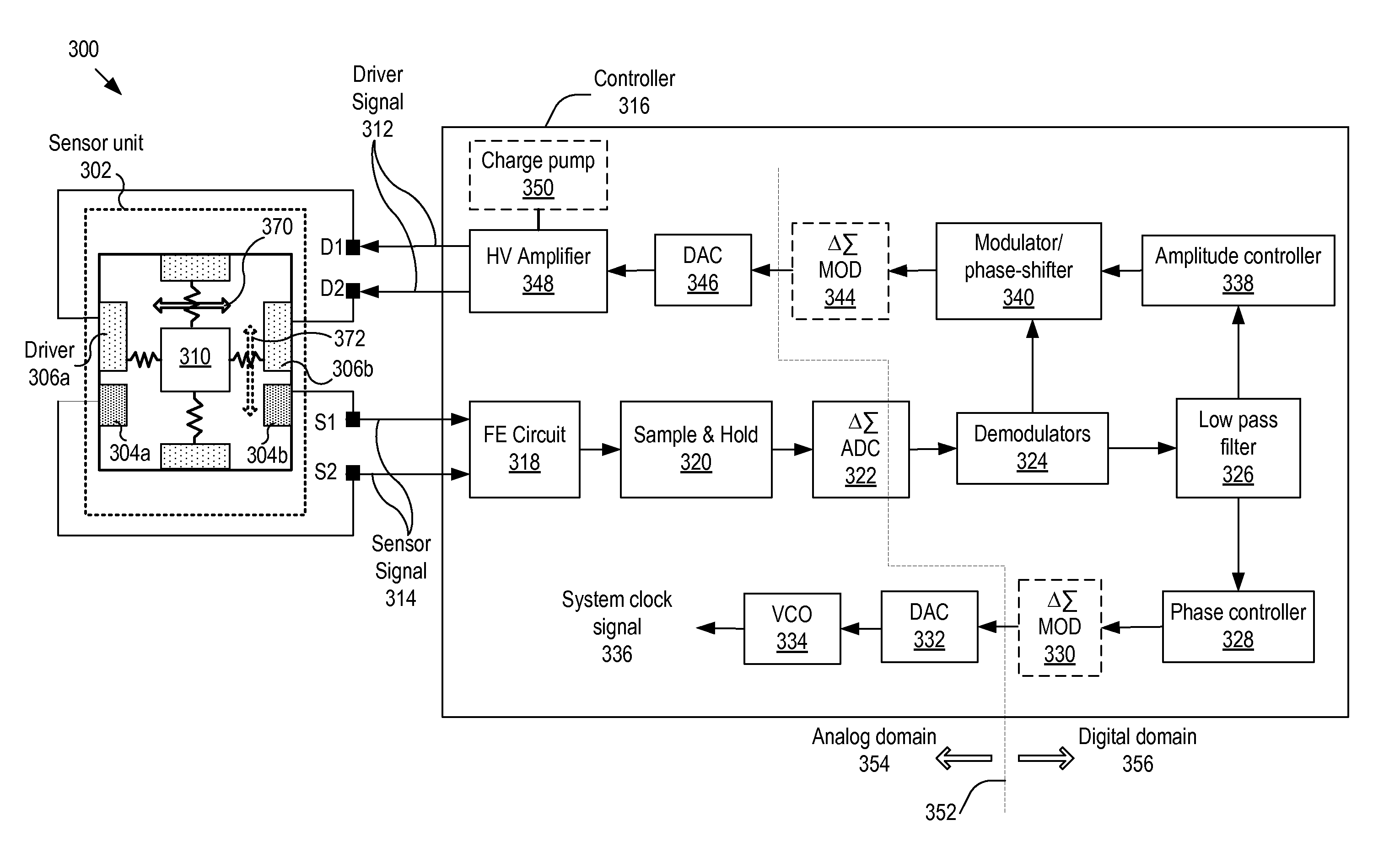
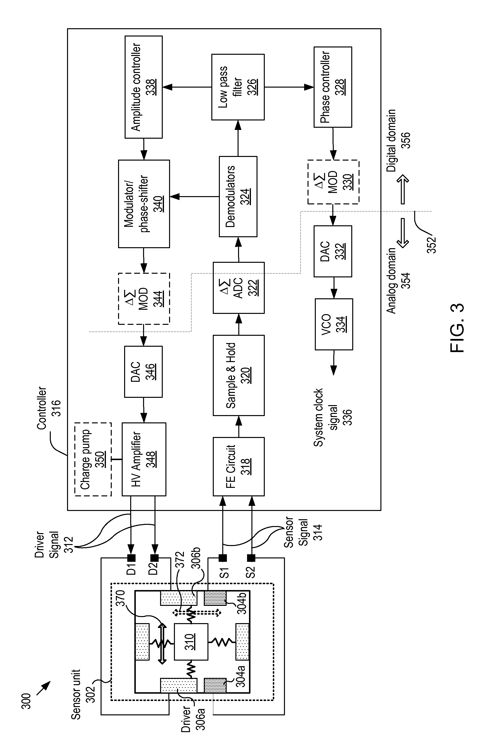
The invention relates to a controller, and more particularly, to systems, devices and methods of controlling a sensor having a resonating mass. The controller includes: an analog-to-digital converter (ADC) unit for extracting a digitized sensor signal from the sensor signal; a phase controller for generating, based on the digitized sensor signal, a phase-controlled signal that is locked in phase with the digitized sensor signal; an amplitude controller for applying a gain to the digitized sensor signal to thereby generate an amplitude-adjusted signal; a modulator for modulating the amplitude-adjusted signal to thereby generate a modulated signal; and a phase shifter for shifting the phase of the modulated signal by 90 degrees. The output signal from the phase shifter is amplified and input to the drive for exciting the resonating mass, to thereby form a closed resonance loop for controlling the oscillation amplitude of the resonating mass.

Description

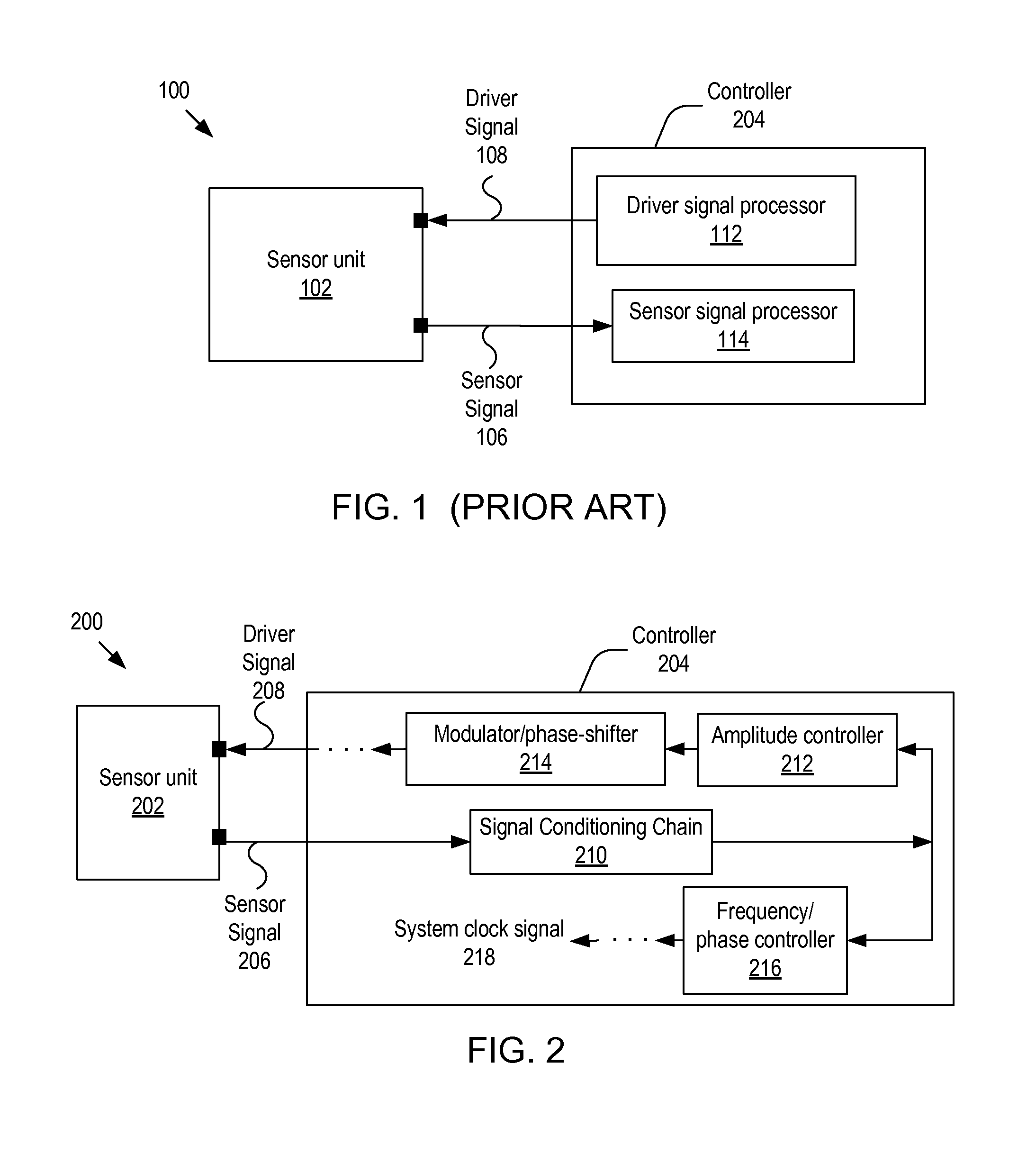
BACKGROUND[0001]A. Technical Field[0002]The present invention relates to a sensor controller, and more particularly, to a controller having a closed loop to control the oscillation amplitude of a resonating mass in a sensor.[0003]B. Background of the Invention[0004]A rate of rotation sensor has been widely applied to measure the angular velocity of a moving object. FIG. 1 shows a schematic diagram 100 of a conventional gyroscope for measuring the rate of rotation of a sensor. As depicted, the conventional gyroscope includes: a sensor signal processor 114 for processing a sensor signal 106 from the sensor of a sensor unit 102; and a driver signal processor 112 for generating and providing a driver signal (or, equivalently, forcing signal or excitation signal) 108 to a driver of the sensor unit 102.[0005]Such a conventional system has several problems. First, the excitation frequency, which is derived from the system clock, may not be close to the resonant frequency under certain circ...

Claims


Application Information

Patent Timeline
IPC IPC(8): H03B5/30
CPCG01C19/567G01P15/14H03B5/30G01C19/5726G01C19/5649G01P15/097G01C19/5776
Inventor CAZZANIGA, GABRIELEFORTE, FEDERICOPRANDI, LUCIANO
Owner HANKING ELECTRONICS LTD
Why Eureka
Eureka Blog
Learn More