
Switchable luminescent see-through system

a luminescent system and switchable technology, applied in the field of switchable switchable luminescent systems, can solve the problems of limited application flexibility of luminescent materials realized in this way as decorative elements, application on transparent surfaces, milky or yellow background appearance, etc., and achieve the effect of imparting luminescent properties and high transparency

Inactive Publication Date: 2014-09-25
HELIV GRP SRL
View PDF3 Cites 19 Cited by
  • Summary
  • Abstract
  • Description
  • Claims
  • Application Information

AI Technical Summary

Benefits of technology

The present invention provides a switchable see-through luminescent system that can be activated on command with various electromagnetic radiation sources. The system is transparent in the non-excited state and presents a high level of transparency under non-excited conditions. The luminescent material used in the system must not significantly induce the diffusion of visible light and must have a low absorption spectrum in the visible region to avoid a visible coloring of the system in the off-state. During excitation, the light is guided exclusively by the support material and not by the matrix in which the luminophore agents are dispersed. The system can be applied on the transparent surfaces of materials already installed without the need for their disassembly. The system displays various colors under excited state conditions and can be adapted accordingly for the contest in which the system is placed.

Problems solved by technology

Notwithstanding varying solutions of these being known in the current state of the art, they are of limited application on transparent surfaces, as the matrix in which the dyes of luminophore agents are dissolved, present a milky or yellowed background appearance in their off-state when excitation is absent.
Nevertheless, luminescent materials realized in this way have limited application flexibility as decorative elements, since they cannot be applied to already mounted structures such as shop windows, given that it is not possible to inject the radiation of light generated from the source with a suitable angle, in an efficient mode to generate adequate luminescence.
This arrangement represents a serious drawback in many applications, for instance where large or geometrically complex surfaces are required to present the signally visual effect, and the LED light, or other suitable light source, has to be physically separated from said surfaces.
This solution known to the state of the art, despite allowing an elevated flexibility of realizable shapes is not applicable on already mounted structures, e.g. shop windows, as such that the luminophore agents are dispersed in the body of the material, a condition which limits the transparent material to being that of plastic.
In addition, the fluorescent paints cited (i.e. STROBLITE, UV BLACKLIGHT Tempera Paint, Invisible Blue). are not transparent and are visibly white under normal lighting conditions.
Finally this patent claims a display that is made up of numerous layers and does not present an overall transparency (i.e. see-through is not possible).
Therefore the assembly for the display apparatus according to JP2000276084 do not present an overall transparency and seeing-through said display apparatus is not possible.
However, it requires specific coater or facilities and only certain transparent base materials can be coated with the claimed paint formulation as the enhancement of the mechanical adhesion to the base requires a high-temperature treatment (in the range 150 e 300 degree C.) not suitable for application on polymeric transparent surfaces (e.g. a methacrylate partition) nor on already mounted structures (e.g. a shop windows).
This solution, despite allowing an elevated flexibility of realizable shapes, is not applicable on existing structures, e.g. shop windows, as such that the luminophore agents are dispersed in the body of the material, a condition which limits the application to polymeric transparent materials.

Method used


Image

  • Switchable luminescent see-through system
  • Switchable luminescent see-through system
  • Switchable luminescent see-through system

Examples


first embodiment

[0035]With reference to the above cited figures, a switchable see-through luminescent system according to the present invention, characterized by the fact that it presents itself in two states, transparent in its ‘off-state’ and luminescent in its ‘on-state’ in accord with the presence or absence of suitable excitation is indicated in a first embodiment with the number (1). Such switchable luminescent system (1) comprises support means (10) having an arbitrary shape delimited with one or more surfaces (11). As an indicative non-limiting example of the present invention, the said support means (10) is essentially realized with transparent materials, preferably glass, quartz crystal, glass ceramics, transparent or semi-transparent plastics such as poly(methyl methacrylate), polycarbonate, polyvinyl butyral or combinations of these. These materials, depending on the case, can be treated by means of tempering, coating or other current state-of-the-art processes to adapt their mechanical...

second embodiment

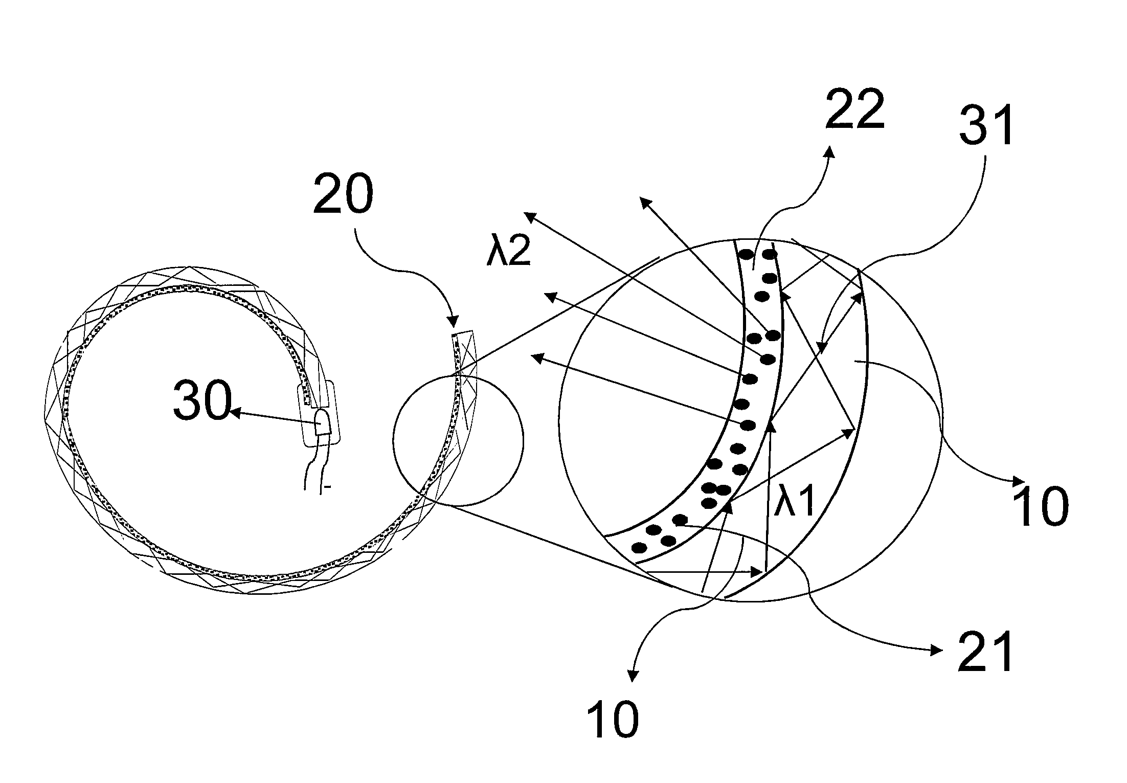
[0038]In the present invention, depicted in FIG. 2 and therein indicated by number (2), the configuration ‘edge light injection’ is schematically shown, where the transparent support (10) would be a flat plate of laminated glass. Such embodiment of the current invention, intended as an indicative non-limiting example, discloses a transparent support (10), in the form of laminated glass where the transparent support, (10) comprising the luminescent material (20) is applied on the surface (11) between a suitable laminating layer. Said luminescent material (20) appears luminescent when advantageously excited by electromagnetic radiation (30). Once the transparent support (10) becomes a luminous source, its transparency is noticeably reduced and / or cancelled.

third embodiment

[0039]In the present invention, depicted in FIG. 3 and therein indicated by number (3), the configuration ‘edge light injection’ is schematically shown, where the transparent support (10) would be a double glazed glass unit. In all embodiments 1, 2 and 3, the coloring is obtained from the particular combination of different luminescent or fluorescent substances (21) with the excitation sources (30) used. Advantageously, the system as it is described in its first three embodiments, illustrating the invention, made by way of an indicative non-limiting example without, is suitable as an architectural element for glass structured facades in buildings, or as illuminating partition walls for open-space offices, as screens for shower boxes and sanitary units or additionally as a system of diffuse lighting, imparting novel functionality by being switchable, for architectural elements and existing transparent furnishings in a given setting.


PUM


Abstract

The present invention relates to a switchable see-through luminescent system, e.g. for luminous signage, characterized by its mode to exist in two different states, transparent (‘off-state’) and luminescent (‘on-state’), due to the presence of a luminescent material (20), coated on to the transparent surface (10), capable of being excited on command by means of lighting sources (30) (e.g. LEDs) characterized by suitable emission spectra. In the off-state of the luminescent material (20), the surface appears transparent and it is not evident any significant modifications of the optical properties (transparency, color, etc.) of the surface. The excitable luminescent material, from which a large variety of luminophores can be conveniently applied on to a substantially transparent support, of arbitrary geometry, realized with a plurality of homogenous and heterogeneous materials, including laminated glass or double glazed windows, provides a large variety of possible shapes capable of satisfying varied application requirements.

Description

TECHNICAL FIELD[0001]The present invention relates to an excitable switchable see-through luminescent system that can be applied on a transparent support base, such as a shop window, for visualization on command of luminescent graphic elements once these have been effectively excited by a suitable source of electromagnetic radiation. The said system is, for example, applicable in the field of signage, publicity, visual communication, furniture and lighting.BACKGROUND ART[0002]The problem of modifying a transparent body to obtain a diffused light sources has been addressed in a variety of ways. According to the current state of the art, it is possible to use different solutions to illuminate plastic or other materials by exploiting the phenomenon of luminescence or fluorescence produced by opportunely excited chemical compounds, typically from light radiation generated by LEDs. In general terms, the solutions known in the art can be divided in two broad categories.[0003]A first kind ...

Claims


Application Information

Patent Timeline
Patent Type & Authority Applications(United States)
IPC IPC(8): G09F13/18F21V8/00G09F13/20F21V9/00
CPCG09F13/18G09F13/20G02B6/0035F21V9/00G02B6/0028G09F2013/222
Inventor RIELLO, PIETROENRICHI, FRANCESCOBELLOTTO, LUCAFRERIS, ISIDORABELLAN, SIMONE
Owner HELIV GRP SRL
Learn More