Mass selector, and ion gun, ion irradiation apparatus and mass microscope
a technology of ion irradiation apparatus and mass microscope, which is applied in the direction of instruments, particle separator tube details, separation processes, etc., can solve the problems of reducing the accuracy of the position of the object to be processed, the insufficient control of the position accuracy of the object, and the inability to accurately detect the position of the obj
- Summary
- Abstract
- Description
- Claims
- Application Information
AI Technical Summary
Benefits of technology
Problems solved by technology
Method used
Image
Examples
first embodiment
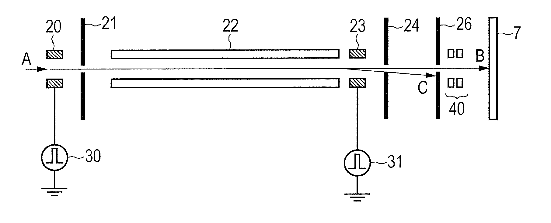
[0045]An ion mass selector in the present embodiment and a method for operating a cluster ion irradiation apparatus having the same will be described below with reference to FIG. 1, while the application to a secondary ion mass spectrometer is taken as an example.
[0046](Operation Principle)
[0047]As is illustrated in FIG. 1A, a cluster ion irradiation apparatus 12 in the present embodiment has a nozzle 2, an ionization section 3, a mass selector 4, a focusing section 5 and an irradiation stage 6, and each part constitutes the whole vacuum chamber 1. In addition, the nozzle 2, the ionization section 3 and the mass selector 4 constitute an ion gun 10. Furthermore, the cluster ion irradiation apparatus 12 in the present embodiment has a not-shown vacuum exhausting system and a signal processing system. An object 7 to be irradiated is installed on the irradiation stage 6.
[0048]Substances that become raw materials of the cluster are supplied to the nozzle 2 through a gas introduction pipe...
second embodiment
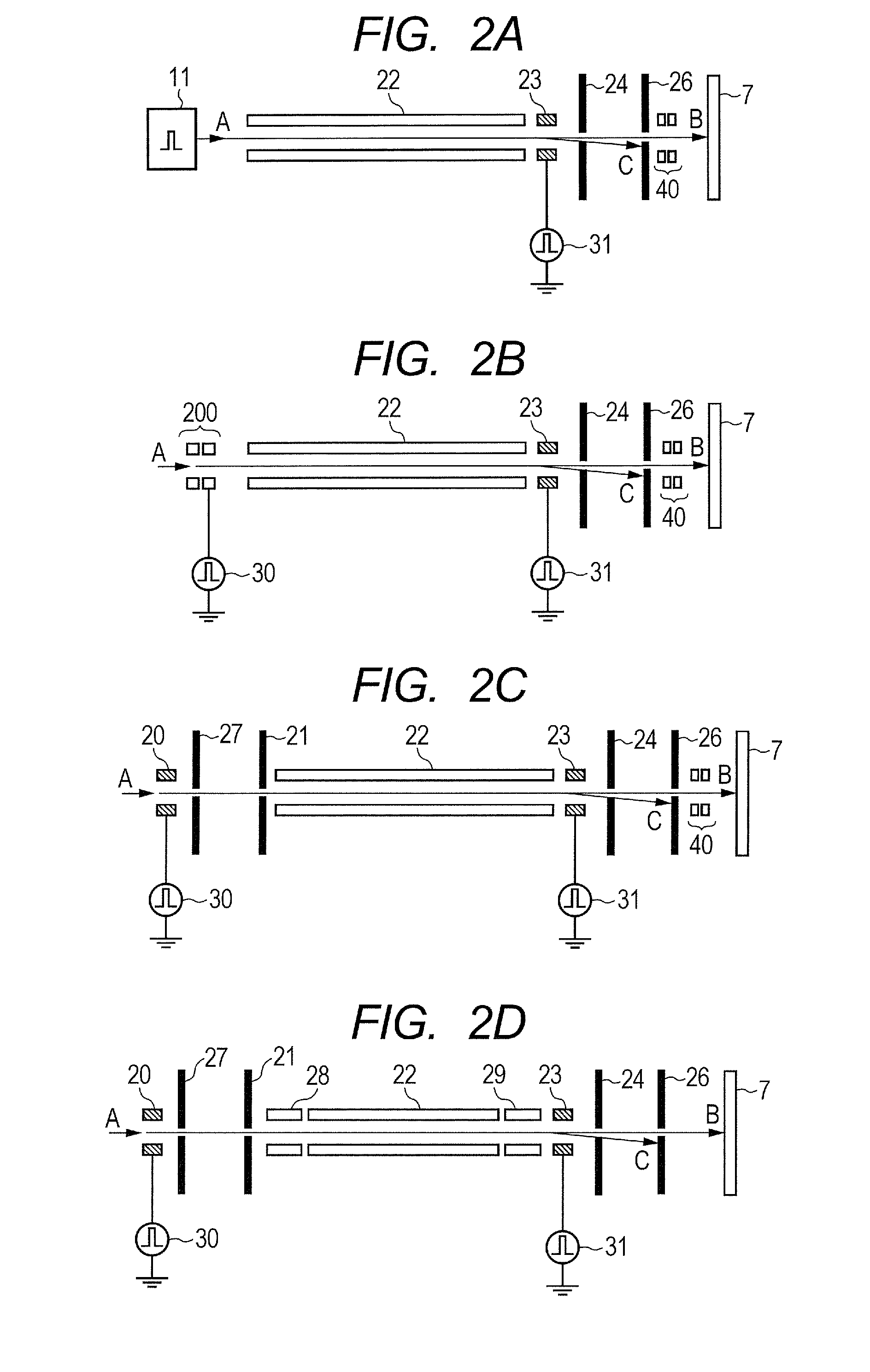
[0104]An ion mass selector (FIG. 2C) according to the present embodiment is similar to that in the first embodiment, except for such a positional relationship among these three devices that an incident side aperture electrode 27 is provided in between the deflector for the trigger 20 and the aperture electrode for the trigger 21.
[0105]A distance between the deflector for the trigger 20 and the incident side aperture electrode 27 is 5 [mm], and a distance between the incident side aperture electrode 27 and the aperture electrode for the trigger 21 is 34 [mm]. In the present embodiment, the incident side aperture electrode 27 is grounded, but a voltage may be applied thereto.
[0106]A result of an ion-optical simulation for a mass selector in the present embodiment is illustrated in FIG. 3D. Voltages to be applied to each electrode are similar to those in the first embodiment, except that a voltage of + / −25 [V] is applied to the deflector for the trigger 20. In addition, acceleration en...
third embodiment
[0112]An ion mass selector (FIG. 2A) according to the present embodiment is similar to that in the first embodiment, except that the ion mass selector has a pulsed ion source 11 which can generate ions in a pulsing way, in place of the deflector for the trigger 20 and the aperture electrode for the trigger 21.
[0113]The pulsed ion source 11 can generate a cluster ion beam D which has been pulsed so as to have a pulse width equivalent to that of a chopper for a trigger. The pulsed ion source 11 may be a device, for instance, which generates cluster ions by irradiating a gas, a solid or a liquid with laser light or electrons by using a pulsed laser or an electron gun which can be driven in a pulsing way. Furthermore, the pulsed ion source 11 may also be a device which generates a charged droplet, such as an electroinject that applies high voltage to a droplet in a pulsing way.
[0114]Furthermore, the pulsed ion source 11 may also be a device which generates a pulsed cluster ion beam D by...
PUM
 Abstract
Description
Claims
Application Information
 - R&D
- Intellectual Property
- Life Sciences
- Materials
- Tech Scout
- Unparalleled Data Quality
- Higher Quality Content
- 60% Fewer Hallucinations
Browse by: Latest US Patents, China's latest patents, Technical Efficacy Thesaurus, Application Domain, Technology Topic, Popular Technical Reports.
© 2025 PatSnap. All rights reserved.Legal|Privacy policy|Modern Slavery Act Transparency Statement|Sitemap|About US| Contact US: help@patsnap.com


