
Liquid ejecting head, liquid ejecting apparatus, piezoelectric element, and ultrasonic sensor

Active Publication Date: 2014-08-28
SEIKO EPSON CORP
View PDF2 Cites 14 Cited by
  • Summary
  • Abstract
  • Description
  • Claims
  • Application Information

AI Technical Summary

Benefits of technology

The invention prevents the performance of a liquid ejecting head, a liquid ejecting apparatus, a piezoelectric element, and an ultrasonic sensor from deteriorating due to heat generated during operation.

Problems solved by technology

The increase in the electric capacitance leads to an increase in a calorific value of the piezoelectric element, and accordingly, there is a problem in that a performance of the piezoelectric element deteriorates due to the heat generation.
In addition, there are problems in that a performance of an ultrasonic sensor using the piezoelectric element also deteriorates due to the heat generation, and an ink ejecting performance in an ink jet recording head using the piezoelectric element also deteriorates due to the heat generation.
In addition, such a problem exists not only in the ink jet recording head, also in a liquid ejecting head which ejects liquid other than ink.

Method used


Image

  • Liquid ejecting head, liquid ejecting apparatus, piezoelectric element, and ultrasonic sensor
  • Liquid ejecting head, liquid ejecting apparatus, piezoelectric element, and ultrasonic sensor
  • Liquid ejecting head, liquid ejecting apparatus, piezoelectric element, and ultrasonic sensor

Examples


first embodiment

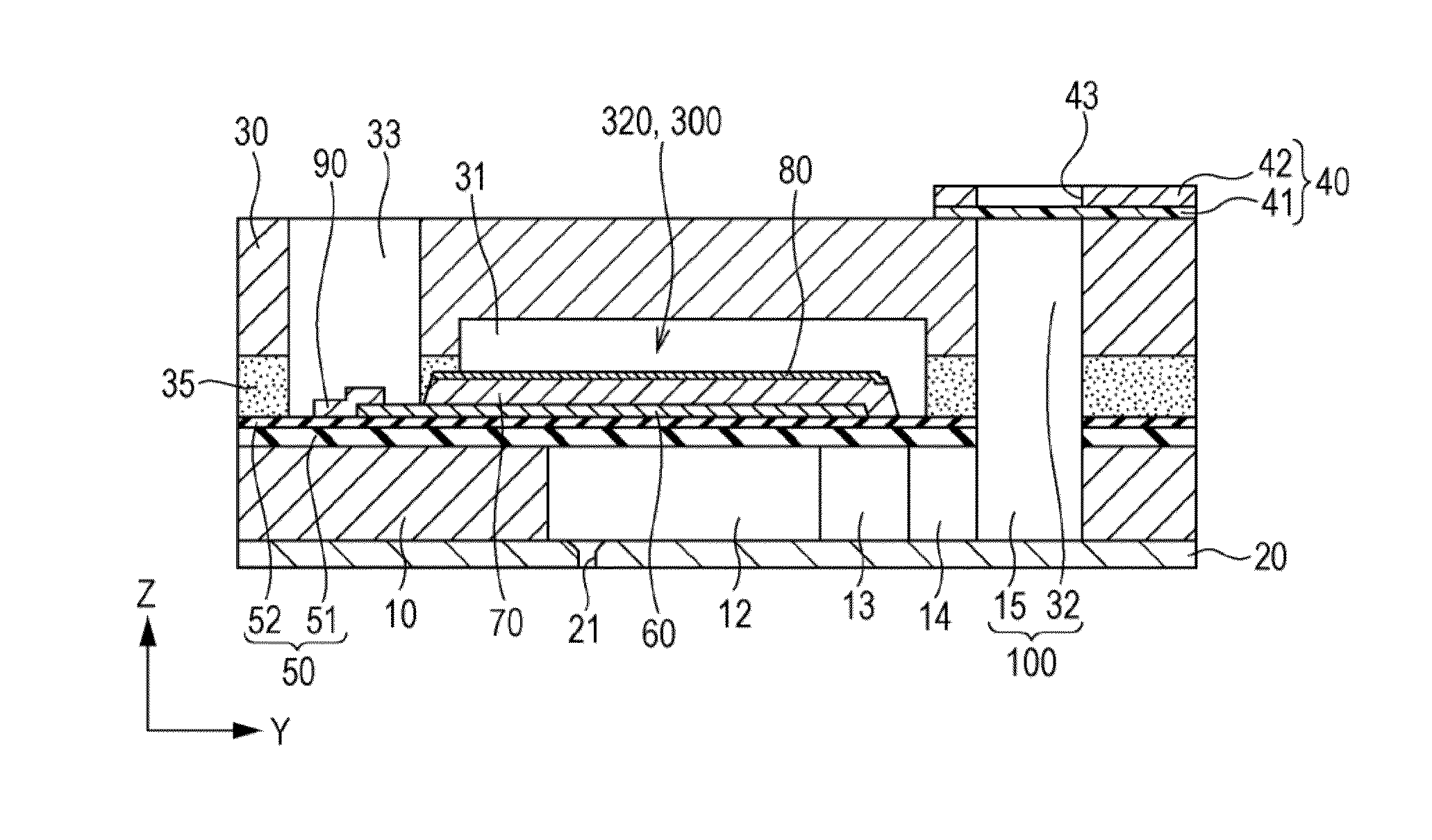
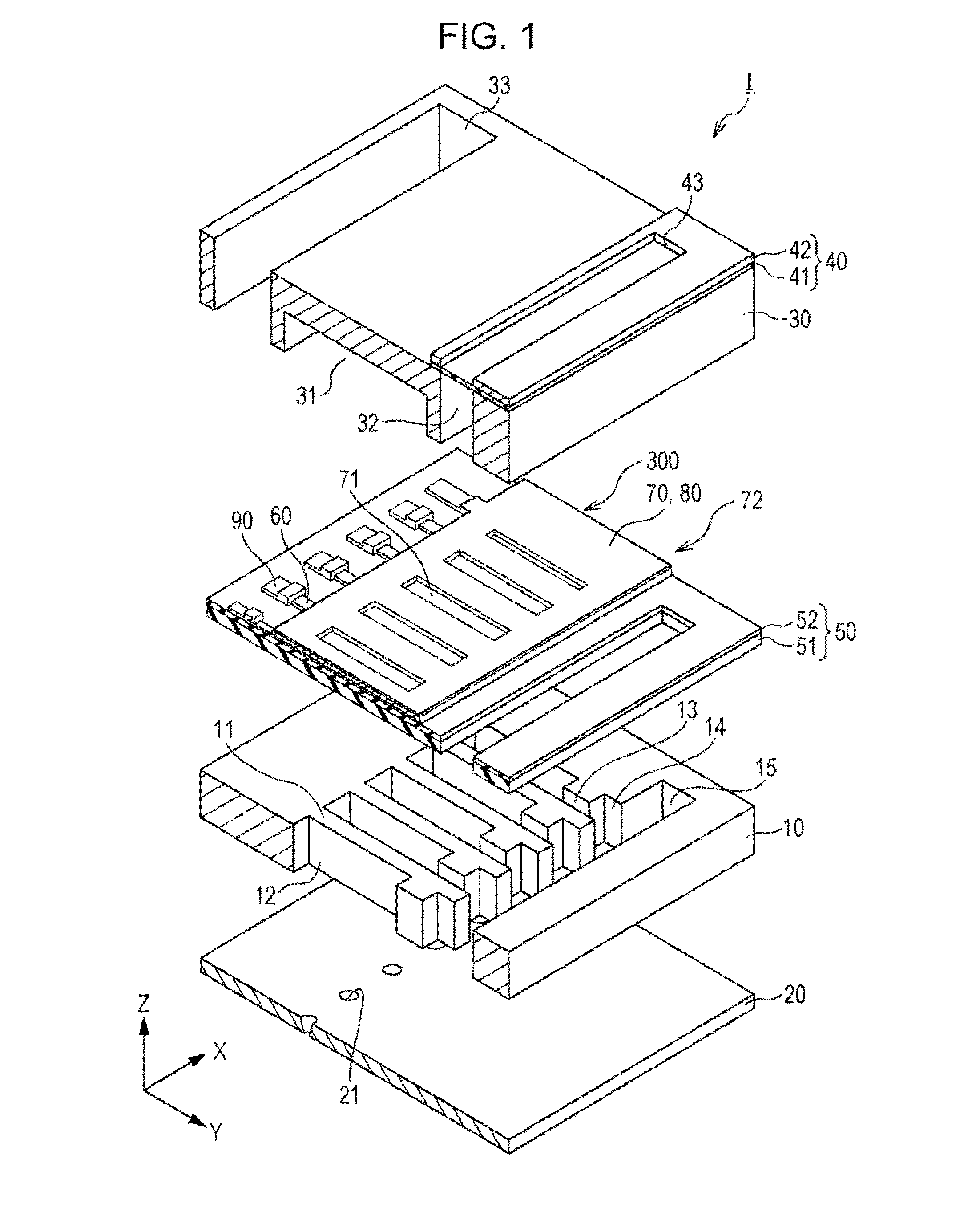
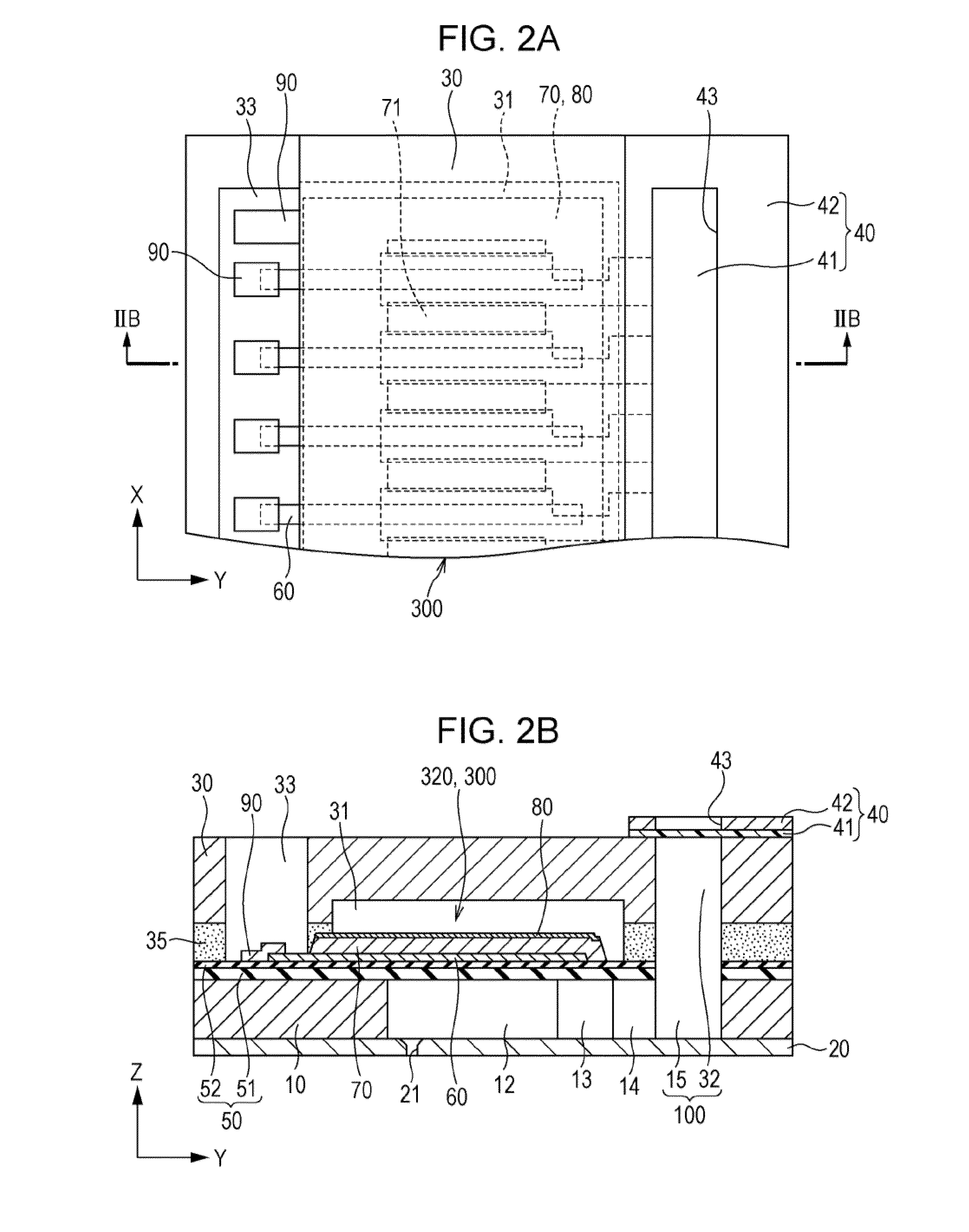
[0044]FIG. 1 is a perspective view of an ink jet recording head as an example of a liquid ejecting head according to a first embodiment of the invention, and FIGS. 2A and 2B are a plan view and a cross-sectional view of the ink jet recording head.

[0045]As illustrated, a pressure generating chamber 12 is formed on a flow path forming substrate 10 which is included in an ink jet recording head I as an example of a liquid ejecting head according to the embodiment. In addition, the pressure generating chamber 12 which is partitioned by a plurality of partitioning walls 11 is aligned along a direction in which a plurality of nozzle openings 21 which eject ink of the same color are aligned. Hereinafter, the direction is referred to as an aligning direction of the pressure generating chamber 12, or a first direction X. In addition, a direction which is orthogonal to the first direction X in a plane of the flow path forming substrate 10 is set to a second direction Y. In addition, a directi...

second embodiment

[0110]In the embodiment, in the manufacturing method of the ink jet recording head which is described in the first embodiment, another type of a process of forming the groove 77 on the side surface of the piezoelectric layer 70 will be exemplified. FIGS. 11A to 11C are cross-sectional views in the first direction X which illustrate a manufacturing method of an ink jet recording head.

[0111]First, similarly to the first embodiment, a first electrode 60 and a piezoelectric layer 70 are formed on an insulating film 52 (refer to FIGS. 7A to 8B).

[0112]Subsequently, as illustrated in FIG. 11A, a first layer 81 which configures a part of the second electrode 80 is formed on the piezoelectric layer 70. Specifically, platinum, iridium, or the like, is formed as a film on the piezoelectric layer 70 using a sputtering method, a physical vapor deposition (PVD) method, or the like. In addition, the first layer 81 is formed by patterning platinum, iridium, or the like, using a resist film as a mas...

third embodiment

[0119]According to the first embodiment and second embodiment, the first electrode 60 is set to an individual electrode, and the second electrode 80 is set to a common electrode, however, it may be reversed. FIG. 12 is a cross-sectional view of a piezoelectric element according to the embodiment in the first direction X.

[0120]As illustrated, a first electrode 60 is continuously provided so as to cover each of pressure generating chambers 12 on an insulating film 52, and configures a common electrode which is common to a plurality of piezoelectric elements 300.

[0121]Piezoelectric layers 70 which have grooves 77 on the side surface are individually formed in a region facing each of the pressure generating chambers 12 on the first electrode 60.

[0122]The second electrode 80 is formed on a top face of each of the piezoelectric layers 70. The second electrode 80 is cut into pieces for each pressure generating chamber 12, and configures an individual electrode which is independent in each ...


PUM


Abstract

A liquid ejecting head which includes a piezoelectric element which includes a first electrode, a piezoelectric layer which is provided on the first electrode, and on which a plurality of piezoelectric films are laminated, a second electrode which is provided on the piezoelectric layer, and a plurality of active units which are interposed between the first electrode and the second electrode, and a pressure generating chamber which communicates with nozzle openings which eject liquid, and in which a pressure fluctuation is generated by the piezoelectric element, in which a plurality of grooves with inner faces facing the first electrode side are formed on a side surface of the piezoelectric layer on each interface of each of the piezoelectric films along a first direction and a second direction which cross a third direction which goes from the first electrode to the second electrode.

Description

BACKGROUND[0001]1. Technical Field[0002]The present invention relates to a liquid ejecting head, a liquid ejecting apparatus, a piezoelectric element, and an ultrasonic sensor.[0003]2. Related Art[0004]In the related art, a liquid ejecting head which ejects droplets from a nozzle which communicates with a pressure generating chamber by generating a pressure fluctuation in liquid in the pressure generating chamber by transforming a piezoelectric element has been known. As a representative example thereof, there is an ink jet recording head which ejects ink droplets as droplets.[0005]The ink jet recording head includes, for example, a piezoelectric element on one surface side of a flow path forming substrate on which the pressure generating chamber which communicates with nozzle openings is provided, and ejects ink droplets from nozzles by generating a pressure fluctuation in the pressure generating chamber by transforming a vibrating plate using a drive of the piezoelectric element.[...

Claims


Application Information

Patent Timeline
IPC IPC(8): B41J2/14H01L41/047
CPCB41J2/14201H01L41/047B41J2/055B41J2/14233B41J2/161B41J2/1628B41J2/1629B41J2/1631B41J2/1645B41J2/1646B41J2002/14241H10N30/80H10N30/2047H10N30/082H10N30/704
Inventor FURUYA, NOBORUNAKAYAMA, MASAO
Owner SEIKO EPSON CORP
Learn More