
Combustor can temperature control system

Active Publication Date: 2014-08-28
GENERAL ELECTRIC CO
View PDF11 Cites 22 Cited by
  • Summary
  • Abstract
  • Description
  • Claims
  • Application Information

AI Technical Summary

Benefits of technology

The patent describes a method to reduce coherence and dynamics in a combustor by supplying fuel to two sets of fuel injectors at different temperatures and pressures. This results in a more stable flame and reduced wear and tear on combustor components. The patent also describes a fuel delivery system with separate manifolds for delivering fuel to each set of combustor cans, allowing for better control of fuel quality and composition. Overall, this patent provides a way to improve the performance and longevity of combustor engines.

Problems solved by technology

At particular operating conditions, combustion dynamics at specific frequencies and with sufficient amplitudes, which are in-phase and coherent, may produce undesirable sympathetic vibrations in the turbine and / or other downstream components.
Combustor tuning to protect the turbine buckets, however, may impose severe restrictions on the function and operability of the combustor.
As the combustion dynamics frequency in one combustor is driven away from that of the other combustors, modal coupling of combustion dynamics may be reduced, which, in turn, may reduce the ability of the combustor tone to cause a vibratory response in downstream components.

Method used


Image

  • Combustor can temperature control system
  • Combustor can temperature control system
  • Combustor can temperature control system

Examples


Embodiment Construction

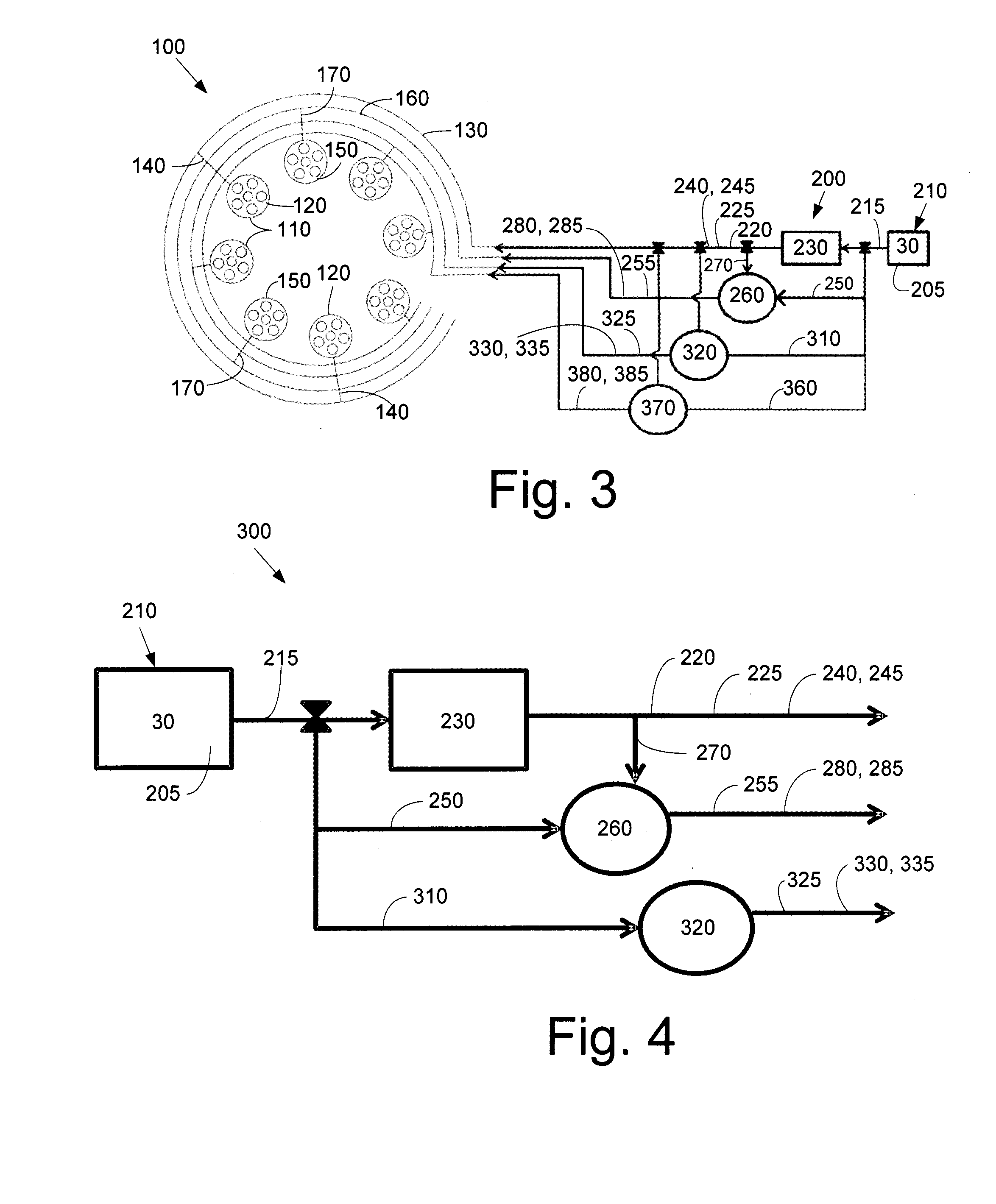
[0017]Referring now to the drawings, in which like numerals refer to like elements throughout the several views, FIG. 1 shows a schematic diagram of gas turbine engine 10 as may be used herein. The gas turbine engine 10 may include a compressor 15. The compressor 15 compresses an incoming flow of air 20. The compressor 15 delivers the compressed flow of air 20 to a number of combustor cans 25. The combustor cans 25 mix the compressed flow of air 20 with a pressurized flow of fuel 30 and ignite the mixture to create a flow of hot combustion gases 35. Although only a single combustor can 25 is shown, the gas turbine engine 10 may include any number of combustor cans 25. The flow of the hot combustion gases 35 is in turn delivered to a turbine 40. The flow of the hot combustion gases 35 drives the turbine 40 so as to produce mechanical work. The mechanical work produced in the turbine 40 drives the compressor 15 via a shaft 45 and an external load 50 such as an electrical generator and...


PUM


Abstract

The present application provides a fuel delivery system for a combustor with reduced coherence and / or reduced combustion dynamics. The combustor can assembly may include a first manifold for delivering a first flow of fuel to a first set of fuel injectors and a second manifold for delivering a second flow of fuel to a second set of fuel injectors. The first flow of fuel may have a first temperature and the second flow of fuel may have a second temperature. The first temperature may be higher than the second temperature.

Description

TECHNICAL FIELD[0001]The present application and the resultant patent relate generally to gas turbine engines and more particularly relate to a can and / or circuit level fuel temperature control system for combustion coherence reduction.BACKGROUND OF THE INVENTION[0002]Combustor cans in a multiple can array may communicate acoustically with each other. Large pressure oscillations, also known as combustion dynamics, may result when heat release fluctuations couple with combustor can acoustic tones. At particular operating conditions, combustion dynamics at specific frequencies and with sufficient amplitudes, which are in-phase and coherent, may produce undesirable sympathetic vibrations in the turbine and / or other downstream components. Typically, this problem is managed by combustor tuning. Combustor tuning to protect the turbine buckets, however, may impose severe restrictions on the function and operability of the combustor.[0003]Altering the frequency relationship between two or m...

Claims


Application Information

Patent Timeline
IPC IPC(8): F02C7/24F02C7/224F02C7/228
CPCF02C7/24F02C7/224F02C7/228F05D2260/96F02C7/222
Inventor CROTHERS, SARAH LORISTEVENSON, CHRISTAN XAVIERLEACH, DAVID
Owner GENERAL ELECTRIC CO
Learn More