Power conversion device and power conversion method
- Summary
- Abstract
- Description
- Claims
- Application Information
AI Technical Summary
Benefits of technology
Problems solved by technology
Method used
Image
Examples
first embodiment
Description of First Embodiment
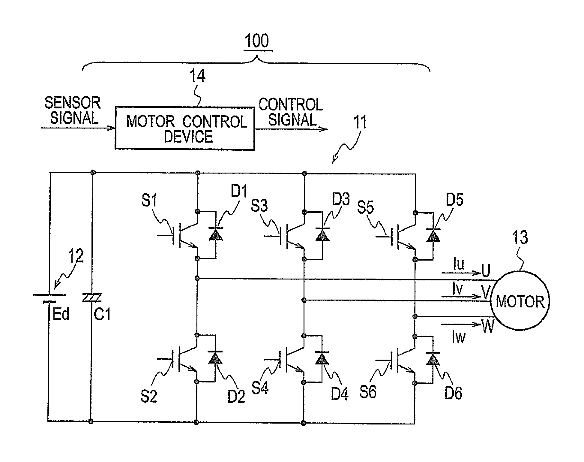
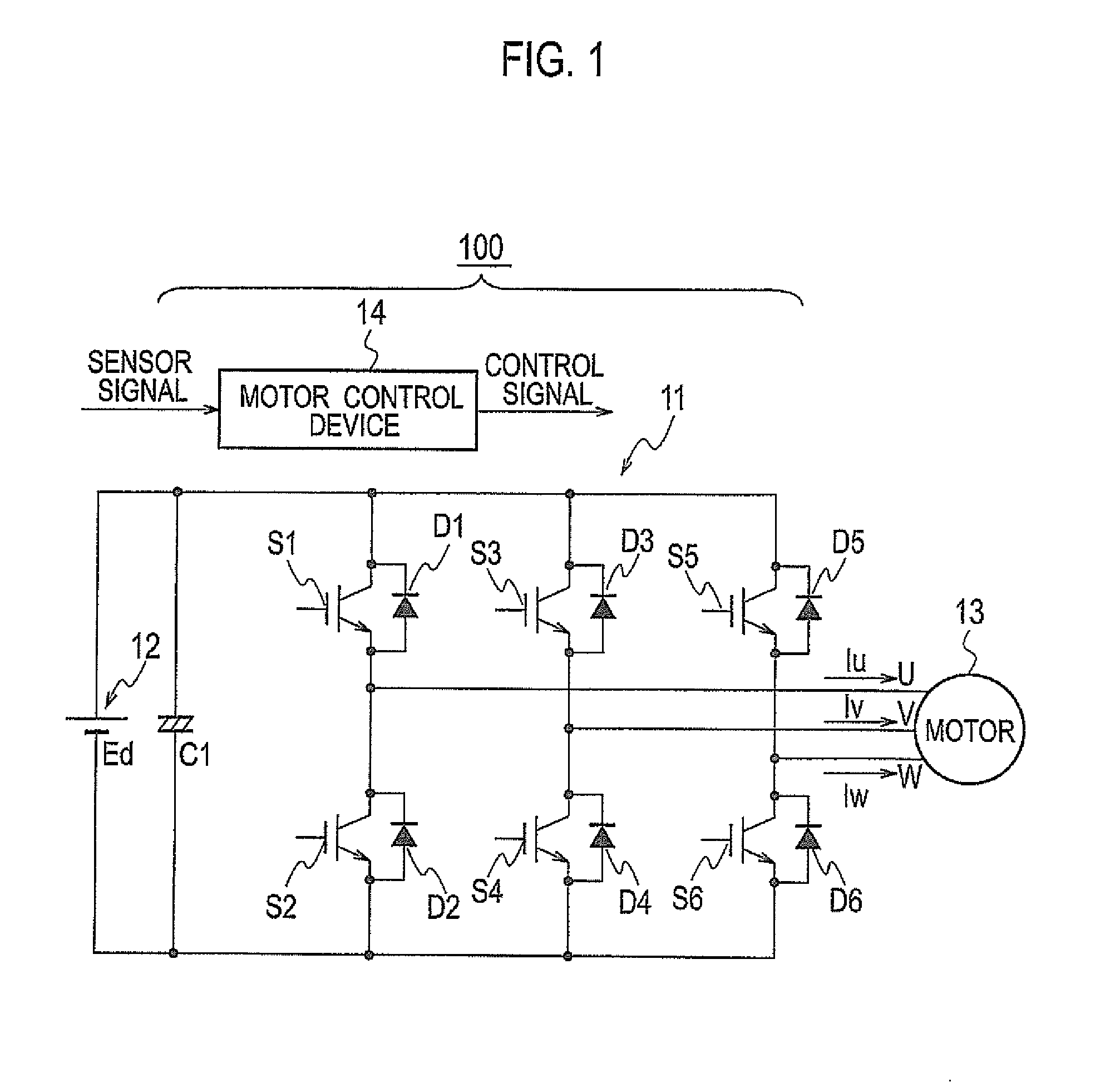
[0027]FIG. 1 is a circuit diagram showing configurations of a power conversion device 100 according to an embodiment of the present invention and of a motor 13 which is driven by receiving power supply from the power conversion device 100. Here, the embodiment shows an example of the power conversion device 100 configured to convert a direct current into a three-phase alternating current. However, the converted alternating current is not limited only to the three-phase alternating current but may also be other polyphase alternating currents having four or more phases.
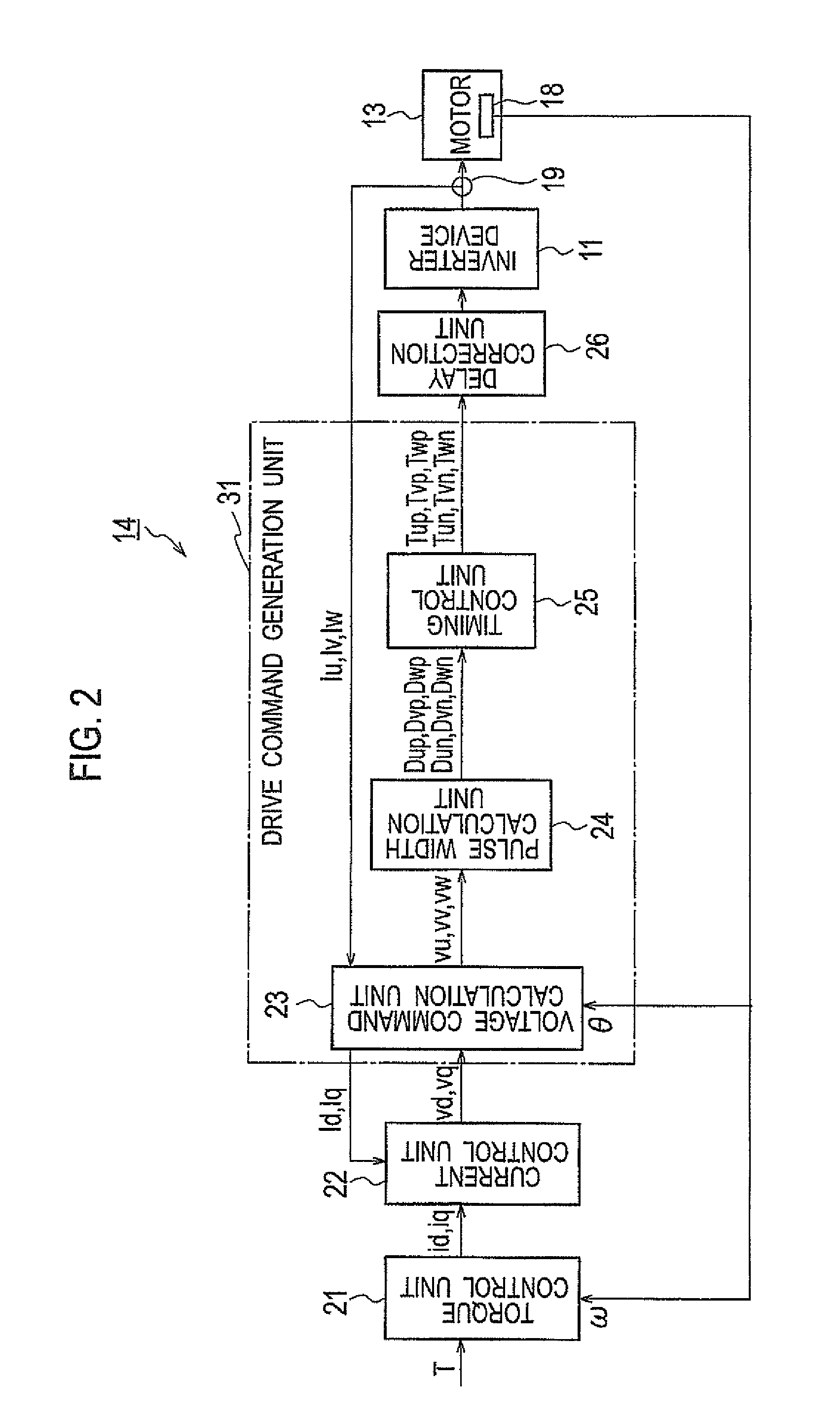
[0028]As shown in FIG. 1, the power conversion device 100 includes an inverter device 11 and a motor control device (a control unit) 14.
[0029]The inverter device 11 includes: a DC power supply 12 configured to supply a DC voltage Ed; and a capacitor C1 connected to the DC power supply 12. The inverter device 11 further includes: switch elements S1, S2, S3, S4, S5, and S6 each using an IGBT...
second embodiment
[0087]Next, a power conversion device according to a second embodiment will be described with reference to FIG. 19. The second embodiment is different in that the delay correction unit 26 shown in FIG. 1 is replaced with a delay correction unit 26a shown in FIG. 19, and in that the switch circuit 41 provided in the inverter device 11 is provided with a voltage sensor (a voltage detection unit) 45. The rest of the configuration is similar to that described in the first embodiment, and descriptions thereof are omitted.
[0088]The delay correction unit 26a shown in FIG. 19 includes a delay time measurement unit 261 and a delay time storage unit 262. The delay time measurement unit 261 measures a time period before the switch element is turned on after a drive command is transmitted to the switch element Sa (a time period required to connect or disconnect the switch element Sa) in an arbitrary control cycle. In the measurement, a voltage between the base and the emitter of the switch elem...
PUM
 Abstract
Description
Claims
Application Information
 - R&D
- Intellectual Property
- Life Sciences
- Materials
- Tech Scout
- Unparalleled Data Quality
- Higher Quality Content
- 60% Fewer Hallucinations
Browse by: Latest US Patents, China's latest patents, Technical Efficacy Thesaurus, Application Domain, Technology Topic, Popular Technical Reports.
© 2025 PatSnap. All rights reserved.Legal|Privacy policy|Modern Slavery Act Transparency Statement|Sitemap|About US| Contact US: help@patsnap.com


