Food kneading appliance
a technology of kneading dough and kneading bowl, which is applied in the direction of clay mixing apparatus, mixing/kneading structural elements, transportation and packaging, etc. it can solve the problems of dough overheating and deteriorating, tiring kneading method, and inability to knead well. , to achieve the effect of reducing the rotation speed
- Summary
- Abstract
- Description
- Claims
- Application Information
AI Technical Summary
Benefits of technology
Problems solved by technology
Method used
Image
Examples
embodiment i
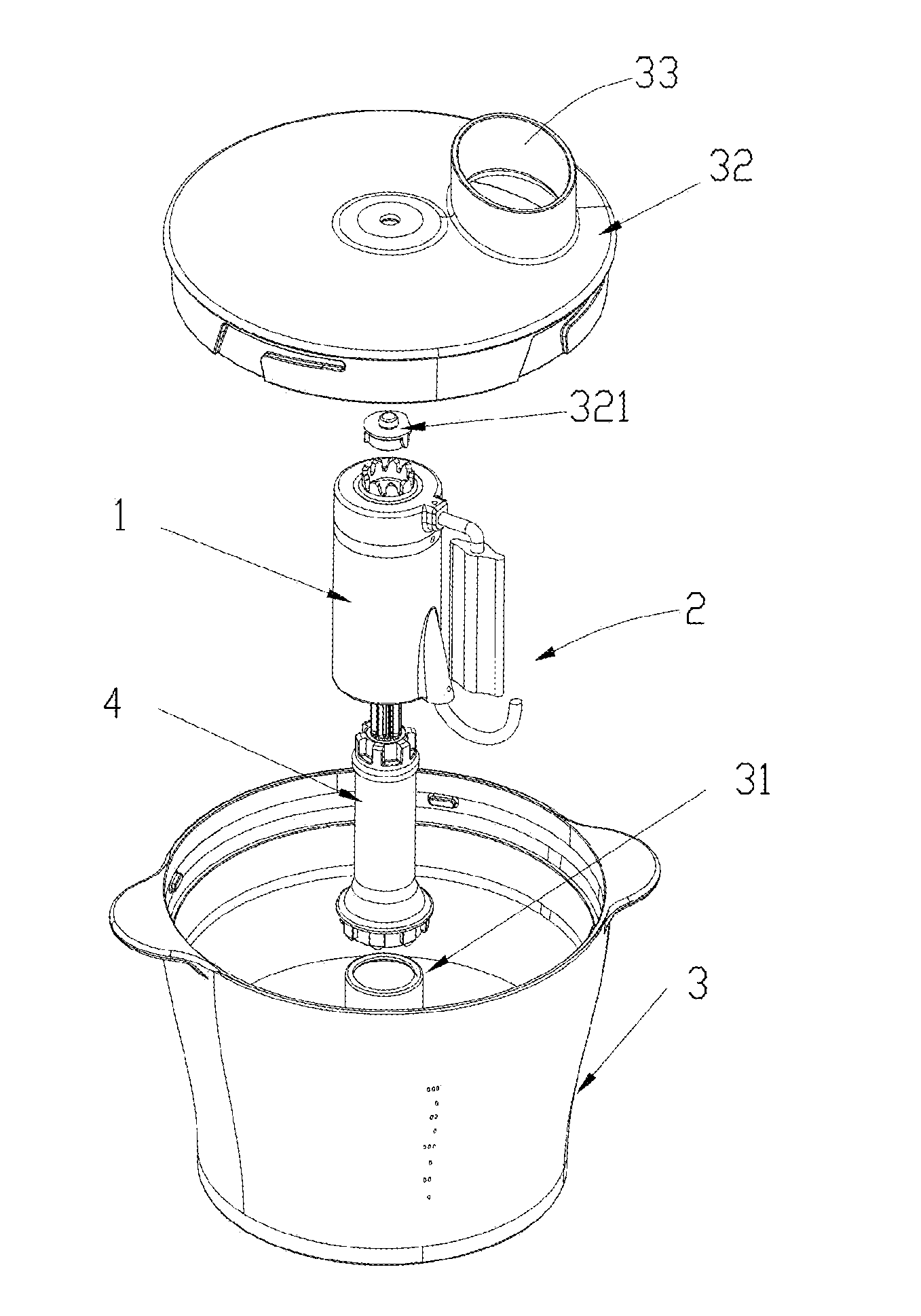
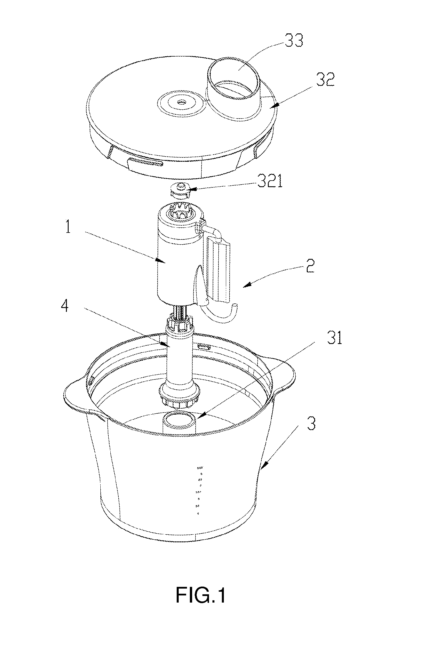
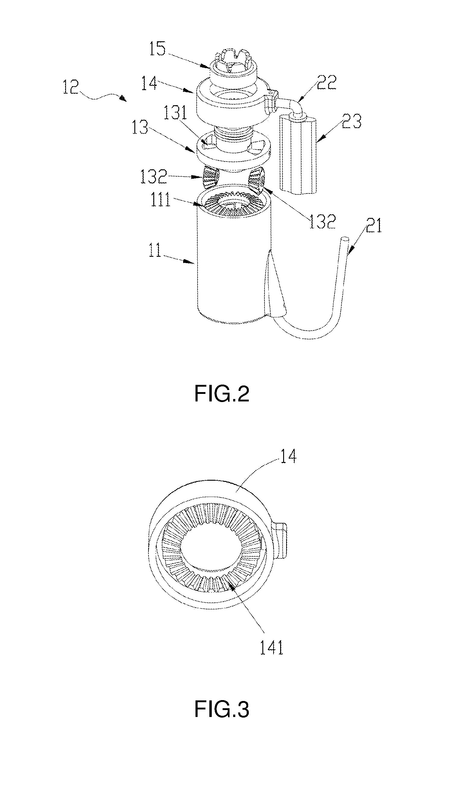
[0024]Referring to FIG. 1 to FIG. 4, a food kneading appliance includes a container 3, a central body 1 located on the center of the container 3, two kneading tools 2 located on the central body 1, and a drive unit for driving the central body 1.
[0025]The central body 1 includes a stirring spindle 11 and a kneading spindle 12 which is configured on the stirring spindle 11. The stirring spindle 11 and the kneading spindle 12 are located in the same axis and rotating in opposite directions in operation.
[0026]The kneading tools 2 include a dough hook 21 disposed on the stirring spindle 11 and a dough mixer 23 disposed on the kneading spindle 12. In the embodiment, the dough hook 21 is substantially J shaped, one end of the dough hook 21 extends downwardly from a lower side of the stirring spindle 11, and then extends upwardly after bending angularly. A substantially inverted L-shape kneading arm 22 is mounted on the outside of the upper kneading spindle 14. The dough mixer 23 is connec...
embodiment ii
[0033]Referring to FIG. 5 and FIG. 6, Embodiment II is similar to Embodiment I on structure, but be different from the shape of the dough mixer 23 which is L-style, and there is no need to set kneading arm. The L-shape dough mixer's 23 horizontal length and bending and vertical length are allowed to be various on design.
[0034]During operation processing, connecting the drive shaft 4 end to the motor, putting the container 3 on the base, then the upper and middle section of the drive shaft 4 protrude through the upper end opening of the hollow cylindrical object 31 of the container 3, the edge of the container's 3 bottom is fixed on the top of the base by locker parts, the central body 1 with kneading tools 2 is held on the hollow cylindrical object 31. Both of guide rails and guide grooves in the drive shaft 4 and the stirring spindle 11 are assembled each other. The drive shaft 4 is held in the connector 15 with the same axis, both of them are locked with the locker which is on the...
PUM
| Property | Measurement | Unit |
|---|---|---|
| angle | aaaaa | aaaaa |
| shape | aaaaa | aaaaa |
| L-shape | aaaaa | aaaaa |
Abstract
Description
Claims
Application Information
 - R&D
- Intellectual Property
- Life Sciences
- Materials
- Tech Scout
- Unparalleled Data Quality
- Higher Quality Content
- 60% Fewer Hallucinations
Browse by: Latest US Patents, China's latest patents, Technical Efficacy Thesaurus, Application Domain, Technology Topic, Popular Technical Reports.
© 2025 PatSnap. All rights reserved.Legal|Privacy policy|Modern Slavery Act Transparency Statement|Sitemap|About US| Contact US: help@patsnap.com


