
System for applying and reading out an information field identifying and protecting an object

a technology of information field and object identification, applied in the field of information technology, can solve the problems of not solving the problem of automated accounting, losing information or counterfeiting, and reducing the accuracy of information, so as to improve the accuracy of information. , the effect of enhancing the functionality

Inactive Publication Date: 2014-07-24
PRYAKHIN EVGENIY IVANOVICH +2
View PDF2 Cites 16 Cited by
  • Summary
  • Abstract
  • Description
  • Claims
  • Application Information

AI Technical Summary

Benefits of technology

The present invention is about a system that can write high-density information on various materials and shapes using a hard / software (H / S) approach. The system can also read and decode the information from the items even under extreme conditions. The decoded information can be saved in a digital form, which enhances its functionality and item identification reliance.

Problems solved by technology

All these methods have a number of disadvantages resulting from their negative effect on the material and a possibility of losing the information or counterfeiting same in case of manufacturing infringing goods.
Besides, those methods fail to solve the problem of automated accounting because the machine-readable marking of products immediately in the process of manufacturing is impossible.
Vendors may face groundless charges resulting from the warranty-based customer return of the goods that in fact were purchased from other companies offering similar products.
Yet, most of the technologies suggest applying the information with various protection levels on intermediate carriers rather than directly on the surface of an item, which seriously compromises the item protection options because, unlike marking the item surface, it does not guarantee the protection element integrity.
The technological result of the inventions is making practically unfeasible to counterfeit, replace or conduct another unauthorized action with regard to the items.
it cannot be used on items made of different materials,
this technical solution cannot be used to protect against counterfeit and to verify the authenticity of items working under extreme environmental conditions (such as high-radioactivity, high temperature and electromagnetic field areas, etc.).
1. The key or the identification code is applied to the item beneath a protection layer that can be damaged when in use and this later may disorientate the authenticity verification;
2. The digital signature is applied onto an intermediate carrier. The intermediate carrier can include a chip or a memory device that are susceptible to electromagnetic field and can be totally destroyed thereby, to computer virus attacks, or to hacking;
3. Accounting and monitoring procedure needs additional barcode printing on intermediate carriers;
4. Authenticity verification is carried out either destroying the protective layer or by a connection to a database through a telecommunication network. In the first case, it is impossible to verify authenticity twice (if the equipment needs to be verified after use), whereas in the second case, the information sent over public networks may be intercepted, computer virus infection is possible, or the database may be tampered with;
5. Subject to operation conditions and product designation, not all items can be provided with a memory device or an information carrier;
6. The memory device or barcode information carrier or additional graphical image with identification data are supposed to be placed either on the item or on the label, tag, etc., making it possible to easily replace or remove the identifying components and thus makes it impossible to verify authenticity or read the information about the manufacturer and / or the item.
7. Without access to a telephone line or the Internet, a user cannot verify the item authenticity.

Method used


Image

  • System for applying and reading out an information field identifying and protecting an object
  • System for applying and reading out an information field identifying and protecting an object
  • System for applying and reading out an information field identifying and protecting an object

Examples


Embodiment Construction

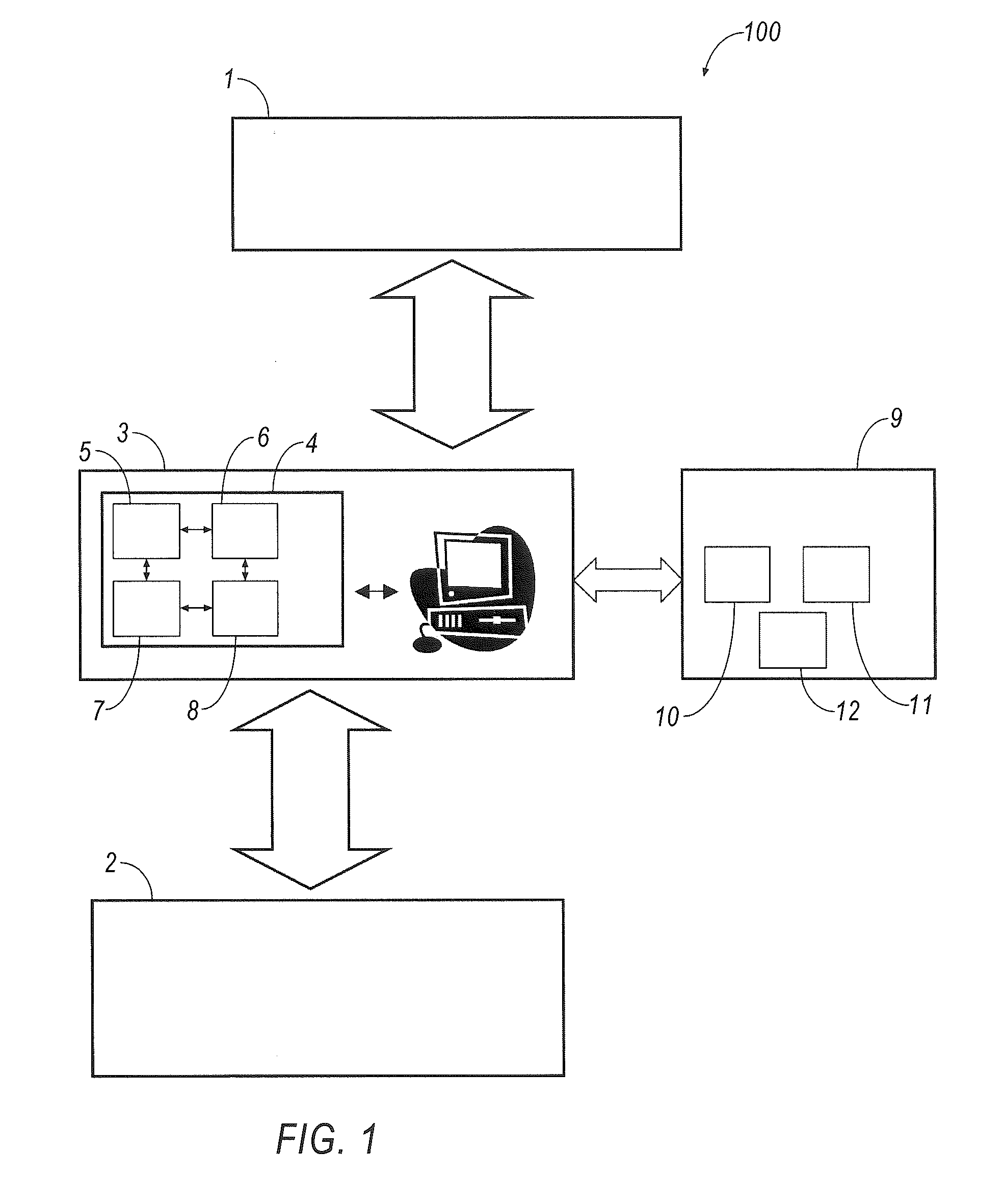
[0076]The hard / software system 100 for forming and reading out information fields with ultrahigh information writing density and enhanced protection according to the present invention is designed using modular architecture and comprises the following units, subunits, and modules: an applying unit 1; a reading unit 2; a control unit 3 with a program subunit 4 that comprises an information encryption module 5, a control script configuration module 6 for the applying unit 1, an image reading and acquiring module 7, and a module 8 for decrypting and outputting information for the reading unit 2; a database unit 9 comprising an information field applying unit database module 10, an item material property database module 11, and an item processing mode database module 12. The module 11 stores information about physical, chemical, and mechanical properties of the material needed for designing processing modes and compiling the processing mode database for the module 12. The module 12 compr...


PUM


Abstract

A hard / software system for applying and reading out an information field identifying and protecting an item, comprises an applying unit, a reading unit, a control unit, and a database unit. The applying unit (for example, a laser or printer) generates the information field and transports it to the item. The control unit comprises an information field data encryption module, a random number generator key, a controlling script configuration module to interact with the applying unit, and a reading and image acquiring module, and a decryption and information output module to interact with the reading unit. The database unit comprises an information field applying unit module, an item material properties module, and an item processing technological mode module for applying the information field. The reading unit can include a digital microscope. The system can apply the information field on various materials, the shape of the item can be plain, cylindrical, etc.

Description

CROSS-REFERENCE TO RELATED APPLICATIONS[0001]This application is a U.S. continuation-in-part National phase application of the International application PCT / RU2011 / 001062, filed Dec. 29, 2011, the entire contents of which International application being hereby incorporated into the present application by reference in full.BACKGROUND OF THE INVENTION[0002]1. Field of the Invention[0003]The present invention relates to information technologies. More particularly, the invention relates to automated systems for the bit data protection and identification when applied directly onto manufactured products. A hard / software system of the present invention is designed for encoding digital information, converting same into an information field with ultrahigh data writing density to be applied directly onto the product surface, as well as for reading out and recognizing the information written earlier. The claimed system can be used not only to identify various items, but also to protect against...

Claims


Application Information

Patent Timeline
Patent Type & Authority Applications(United States)
IPC IPC(8): H04L9/08
CPCH04L9/0816G06K1/126
Inventor PRYAKHIN, EVGENIY IVANOVICHLARIONOVA, EKATERINA VLADIMIROVNAZAHARENKO, EVGENIY ANATOL'EVICH
Owner PRYAKHIN EVGENIY IVANOVICH
Learn More