
Round Baler

a baler and round bale technology, applied in baling, agriculture tools and machines, agriculture, etc., can solve the problems of inability to work out the roller mounted on the spring, high cost, maintenance and other problems, and achieve the effect of reducing the stress on the round bale and avoiding damage to the round bal

Active Publication Date: 2014-07-10
DEERE & CO
View PDF5 Cites 2 Cited by
  • Summary
  • Abstract
  • Description
  • Claims
  • Application Information

AI Technical Summary

Benefits of technology

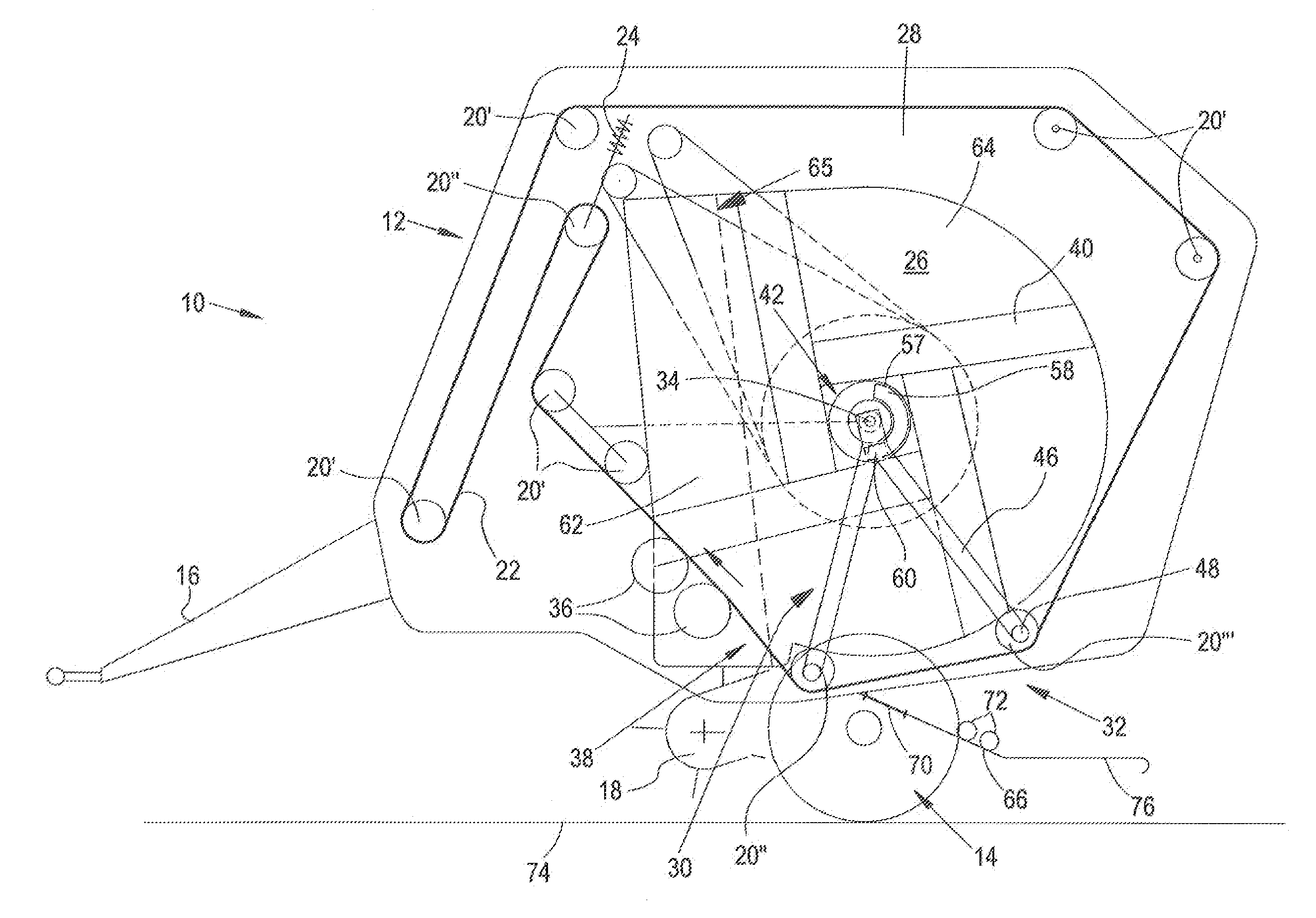
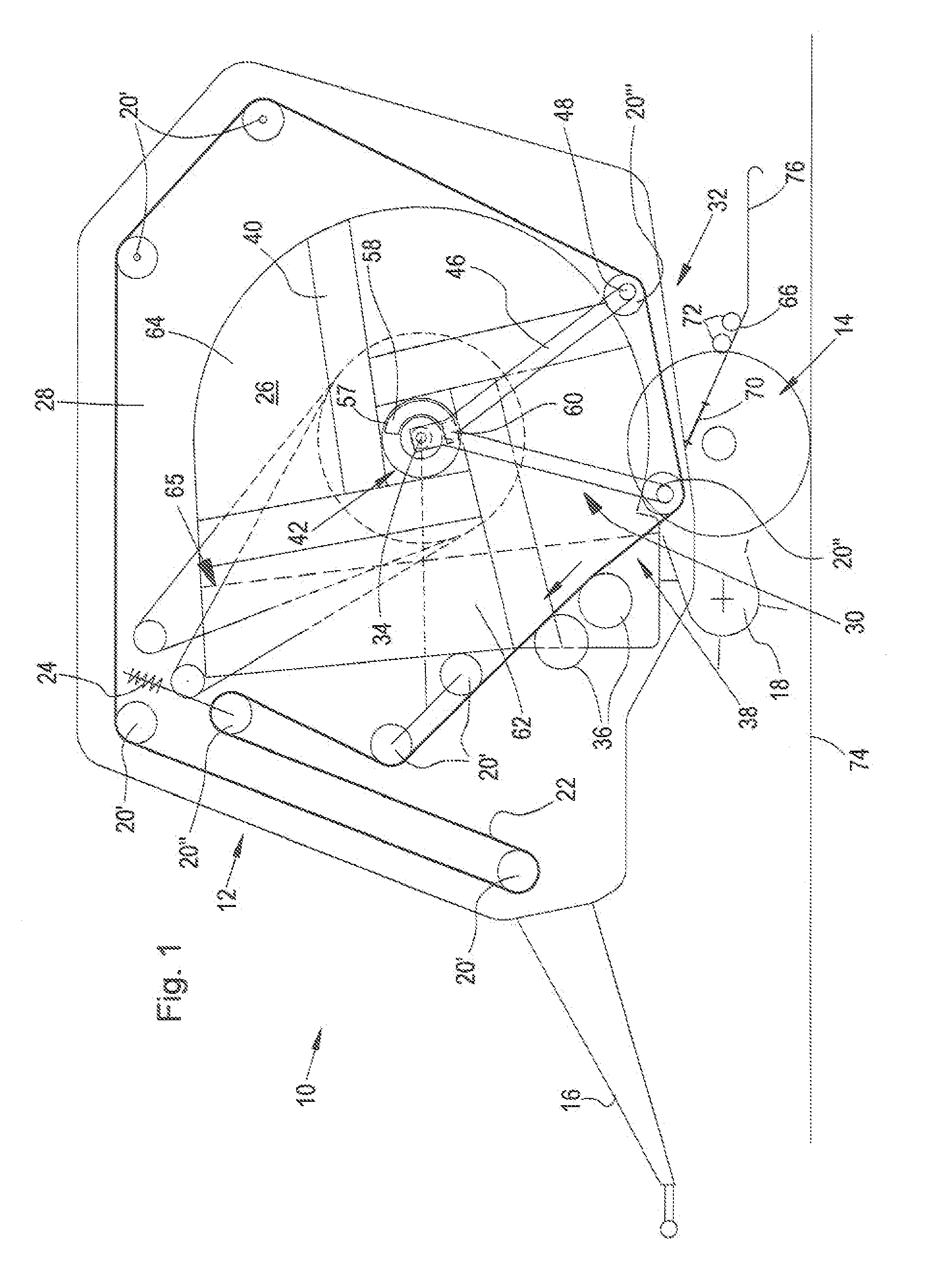
This patent describes a round baler for baling recycling materials. The baler has a flat section with a larger contact area for the round bale, reducing surface pressure and reducing dynamic stress. The round bale is then picked up by a mechanical contact surface that is greater than a roller, reducing mechanical stress on the outer cover or edge layer. The flat section can be provided as a plate, sheet, or other shape. The round bale can also have a resilient layer that can compensate for movement energy and reduce stress on the bale, reducing damage to it during unloading. The resilient layer can be covered with a durable or sturdy film.

Problems solved by technology

A problem arises, in particular, in the case of round bales which are wrapped with a net or twine and are subject to a highly dynamic unloading operation.
The unloading operations encumbered with such extreme changes in direction for the round bale lead to extreme stresses on the round bale which often result in damage to the round bale, in particular to tears in the net or in the twine when the round bale falls onto the depositing elements and is to be transferred from an almost vertical unloading movement into a horizontal unloading movement or rolling movement.
This type of design of a roller mounted on springs works out, however, as structurally expensive, maintenance intensive and susceptible.

Method used


Image

  • Round Baler
  • Round Baler
  • Round Baler

Examples


first embodiment

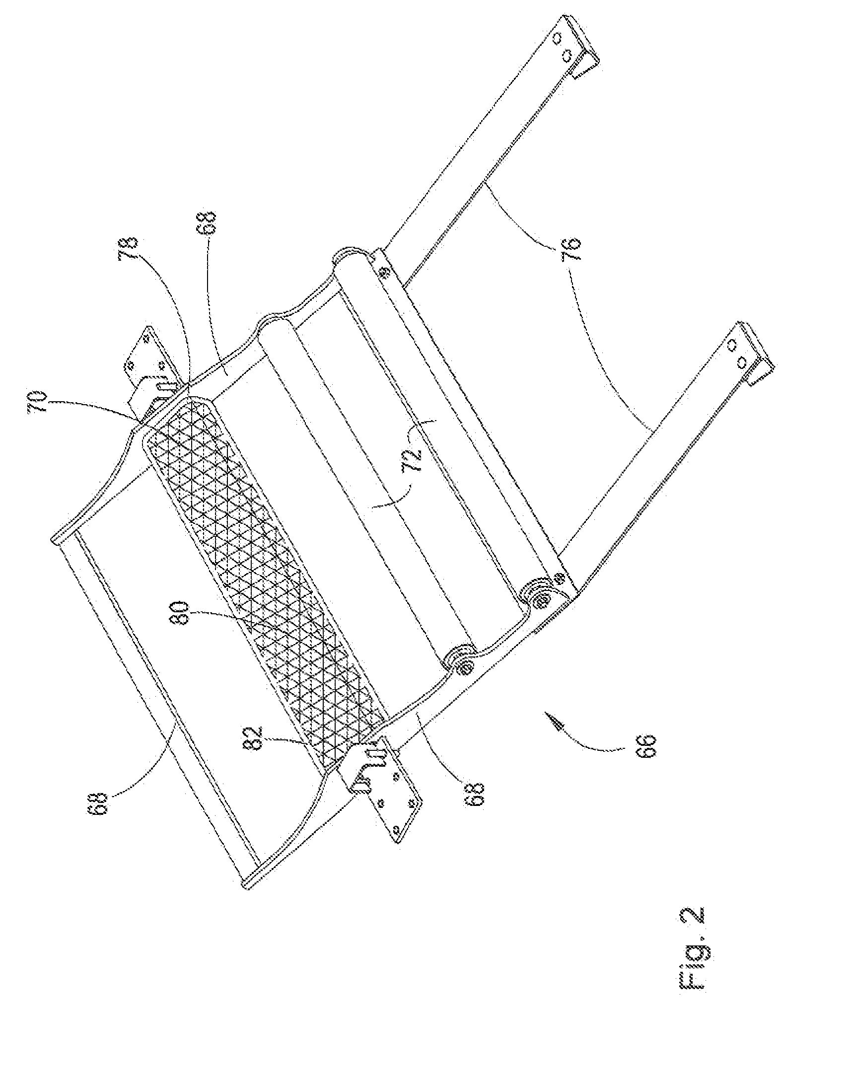
[0040]FIG. 2 shows the depositing element 70. The depositing element 70 is provided as a flat section 78, preferably as a steel plate or steel sheet. The flat section 78 is mounted or fastened at both ends on the ramp frame 68. The depositing element 70 is arranged such that the round bale falls onto the flat section 78 during the unloading operation. In order to move a falling round bale in the direction of the descending unloading ramp 66, the depositing element 70 is preferably arranged in front of the rotational axis of the round bale in the direction of travel. The flat section 78 is surrounded by a resilient layer 80 (shown in a hatched manner in the Figs.), which preferably consists of foam material, but can also be provided from a different resilient material such as, for example, vulcanized rubber or another elastomer. In addition, a covering 82, which is also provided in the exemplary embodiment shown in FIG. 2 as a plate, preferably of plastics material, and covers the re...

second embodiment

[0041]FIG. 3 shows a second embodiment for the depositing element 70 which corresponds to the embodiment from FIG. 2 only that, in this case, the depositing element 70 is provided as a flat section 78′ in the form of a thin steel sheet such that there is no need for a resilient layer 80 and the flat section 78′ in the form of a thin steel sheet itself carries out the resilient deforming under the influence of the weight of the round bale. At the same time, the depositing element 70 or the flat section 78′ is, however, provided in a sufficiently strong manner to withstand the weight of the round bale without plastic deformation. Consequently, part of the energy introduced by the round bale is cushioned. As soon as the round bale has left the depositing element 70, the flat section 78′ assumes its initial form again. In place of a steel sheet, it is also possible to use a plastics material plate with identical resilient characteristics. A covering can be dispensed with in the exemplar...

third embodiment

[0042]FIG. 4 shows a third embodiment for the depositing element 70 which corresponds substantially to the embodiment from FIG. 2 only that, in this case, the depositing element 70, which is provided here as a flat section 78″, is suspended in a pivotable and springy manner. To this end, a first fastening strut 84, which extends parallel with respect to the rotational axis of the round bale and serves as fastening for the depositing element 70, is fastened on the ramp frame 68. The depositing element 70 is fastened by way of pivoting joints 86, for example hinges, on the fastening strut 84 and can be pivoted in a vertical manner. A second fastening strut 88 extends parallel to the first fastening strut 84 on the side of the depositing element 70 opposite the pivoting joints 86. The second fastening strut 88 is fastened at the ends on the ramp frame 68. Spring elements 90, for example spiral springs or helical springs, extend between the depositing element 70 and the second fastening...


PUM


Abstract

A round baler is provided having a frame, a baling chamber on the frame for forming a round bale, an unloading area provided between the baling chamber and a ground surface and at least one depositing element which is arranged in the unloading area and which extends parallel to the rotational axis of the round bale and serves for supporting the round bale during an unloading operation. To reduce mechanical stress on the round bale caused by the depositing element and as a result to prevent damage to the round bale, a flat section is provided which, compared to the rollers otherwise usually used as depositing element, provides a higher contact surface for the round bale such that the surface pressure during the impact of the round bale can be decisively reduced compared to the use of a roller.

Description

FIELD OF THE DISCLOSURE[0001]The disclosure relates to a round baler having a frame, a baling chamber provided on the frame for forming a round bale, an unloading area provided between the baling chamber and a ground surface and at least one depositing element which is arranged in the unloading area and which extends parallel to the rotational axis of the round bale and serves for supporting the round bale during an unloading operation.BACKGROUND OF THE DISCLOSURE[0002]When unloading a round bale out of the baling chamber of a round baler, it is desired to control the movement of the bale. A problem arises, in particular, in the case of round bales which are wrapped with a net or twine and are subject to a highly dynamic unloading operation. During the unloading operation, the round bale, is released from the baling chamber and falls, for example, onto an unloading ramp which is provided with depositing elements which translate the round bale into a controlled rolling movement. Depe...

Claims


Application Information

Patent Timeline
Patent Type & Authority Applications(United States)
IPC IPC(8): A01F15/08
CPCA01F15/0883
Inventor GRESSET, PASCALCHAPON, EMMANUELZABE, MICKAEL
Owner DEERE & CO
Learn More