Weld analysis using laser generated narrowband lamb waves
a laser and lamb wave technology, applied in the field of noncontact generation of lamb waves, can solve the problems of monotonic increase of reflection coefficients and increase of severity, and achieve the effects of reducing signal complexity, allowing flexibility in wavelength selection, and reducing signal complexity
- Summary
- Abstract
- Description
- Claims
- Application Information
AI Technical Summary
Benefits of technology
Problems solved by technology
Method used
Image
Examples
example 1
[0058]To compare the efficacy of the SLS method versus the conventional pattern source method two preliminary experiments were conducted on a 300×200×2 mm aluminum plate. FIGS. 3a and 3b show the schematic of the experiment and the placement of the sensors and the sources for the conventional pattern source (FIG. 3a) and the SLS (FIG. 3b), respectively. FIG. 3a depicts the experiment using a pattern source 220 where the laser beam 205 goes through a mask 210 with eight slits 215. Each slit 215 is 1 mm wide and 15 mm long and the pitch between slits 215 is 2 mm. Also shown is a laser mark 237 of the pattern source 220 on the laser alignment paper 235. The width of each stripe is about 1 mm and the pitch is 2 mm.
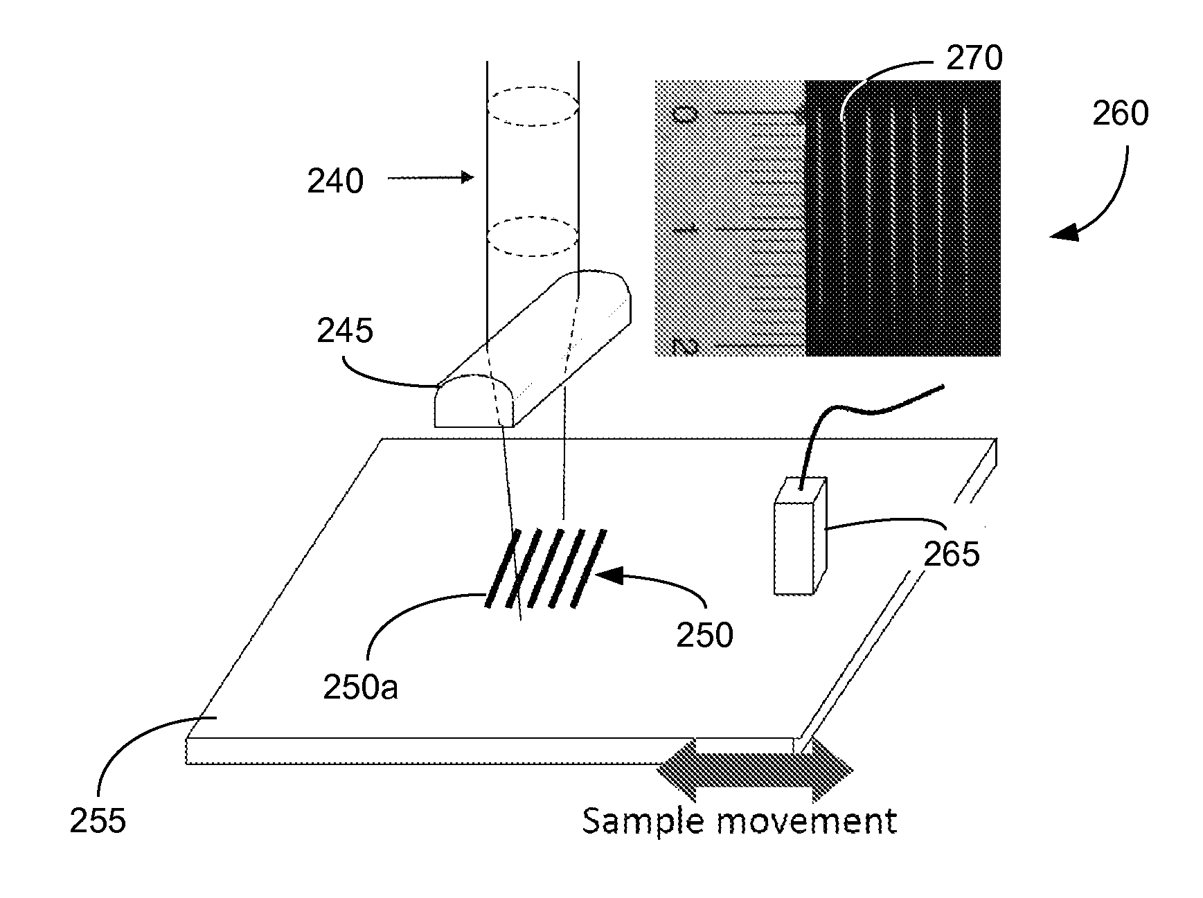
[0059]FIG. 3b shows the experiment using SLS where the laser beam 240 goes through a cylindrical lens 245 and the beam 240 is focused into a line source 250. Laser marks with 2 mm pitch are shown on laser alignment paper 260. Compared with the lines 237 in FIG. 3a, the laser e...
example 2
[0073]A set of finite element simulation on thin plates can be conducted to show that: (1) SLS has practical applications, and (2) the technique of k-ω filtering coupled with continuous wavelet transform can be used to correlate reflection coefficients to defect severity. To simplify problem at hand, the laser line sources are assumed to be infinitely long in the direction orthogonal to the plane defined by wave propagation and thickness. In this way, the problem can be reduced to a 2D plane strain problem. The material used in the simulation is aluminum with the material properties, i.e., longitudinal (CL) and shear (CT) wave speeds, listed in Table 2, below.
TABLE 2Material Properties and Wave SpeedsE (GPa)νλ (GPa)μ (GPa)CL (m / s)CT (m / s)Aluminum700.3351.126.36194.43120.2
[0074]In some embodiments, the simulation of laser generated ultrasound can be approached as a sequentially solved transient thermo-mechanical problem. The temperature field induced by the laser input can first be s...
example 3
[0081]To validate the simulation results, a set of experiments can be conducted. The experimental setup can be the same as the setup depicted in FIG. 5 and the testing procedure can be substantially the same as the procedure previously described. See, “Signal Processing Procedure” section, above. On each sample, an artificial groove is made to simulate a surface breaking defect. In the example, the plate thickness is 2 mm and the grooves are 0.8 mm wide and vary in depth. Seven depths are used in these experiments: 0.25, 0.50, 0.75, 1.00, 1.25, 1.50, and 1.75 mm (i.e., ⅛, 2 / 8, ⅜, 4 / 8, ⅝, 6 / 8 and ⅞ of the plate thickness). A set of five signals that correspond to 2 mm or 3 mm wavelength are superimposed and then processed using the signal processing procedure discussed earlier. Reflection coefficients can then be calculated and compared with simulation results. The results and comparison are shown in FIGS. 11a-11d.
DISCUSSION OF SIMULATION AND EXPERIMENTAL RESULTS
[0082]In FIGS. 10a-1...
PUM
| Property | Measurement | Unit |
|---|---|---|
| Pressure | aaaaa | aaaaa |
| Pressure | aaaaa | aaaaa |
| Pressure | aaaaa | aaaaa |
Abstract
Description
Claims
Application Information
 - R&D
- Intellectual Property
- Life Sciences
- Materials
- Tech Scout
- Unparalleled Data Quality
- Higher Quality Content
- 60% Fewer Hallucinations
Browse by: Latest US Patents, China's latest patents, Technical Efficacy Thesaurus, Application Domain, Technology Topic, Popular Technical Reports.
© 2025 PatSnap. All rights reserved.Legal|Privacy policy|Modern Slavery Act Transparency Statement|Sitemap|About US| Contact US: help@patsnap.com


