
Charge control device for hybrid vehicle

a hybrid vehicle and control device technology, applied in the direction of battery/fuel cell control arrangement, battery/cell propulsion, instruments, etc., can solve the problems of increasing the difficulty of cooling the engine itself, so as to reduce the amount of electric power generation, ensure the cooling performance of the engine, and limit the load on the engine

Active Publication Date: 2014-06-19
MITSUBISHI MOTORS CORP
View PDF38 Cites 16 Cited by
  • Summary
  • Abstract
  • Description
  • Claims
  • Application Information

AI Technical Summary

Benefits of technology

The present invention aims to provide a charge control device for a battery in a hybrid vehicle that can limit the temperature increase of engine cooling water to ensure cooling performance. By controlling the engine speed and power generation, the invention reduces the amount of electric power generated and the load on the engine, thus limiting the temperature increase of the engine cooling water. This ensures cooling performance of the engine and other instruments that are cooled by the cooling system. Additionally, the invention maintains circulation of the engine cooling water and prevents partial temperature increase in the cooling water channel, resulting in increased reliability of alarms based on the temperature of the engine cooling water.

Problems solved by technology

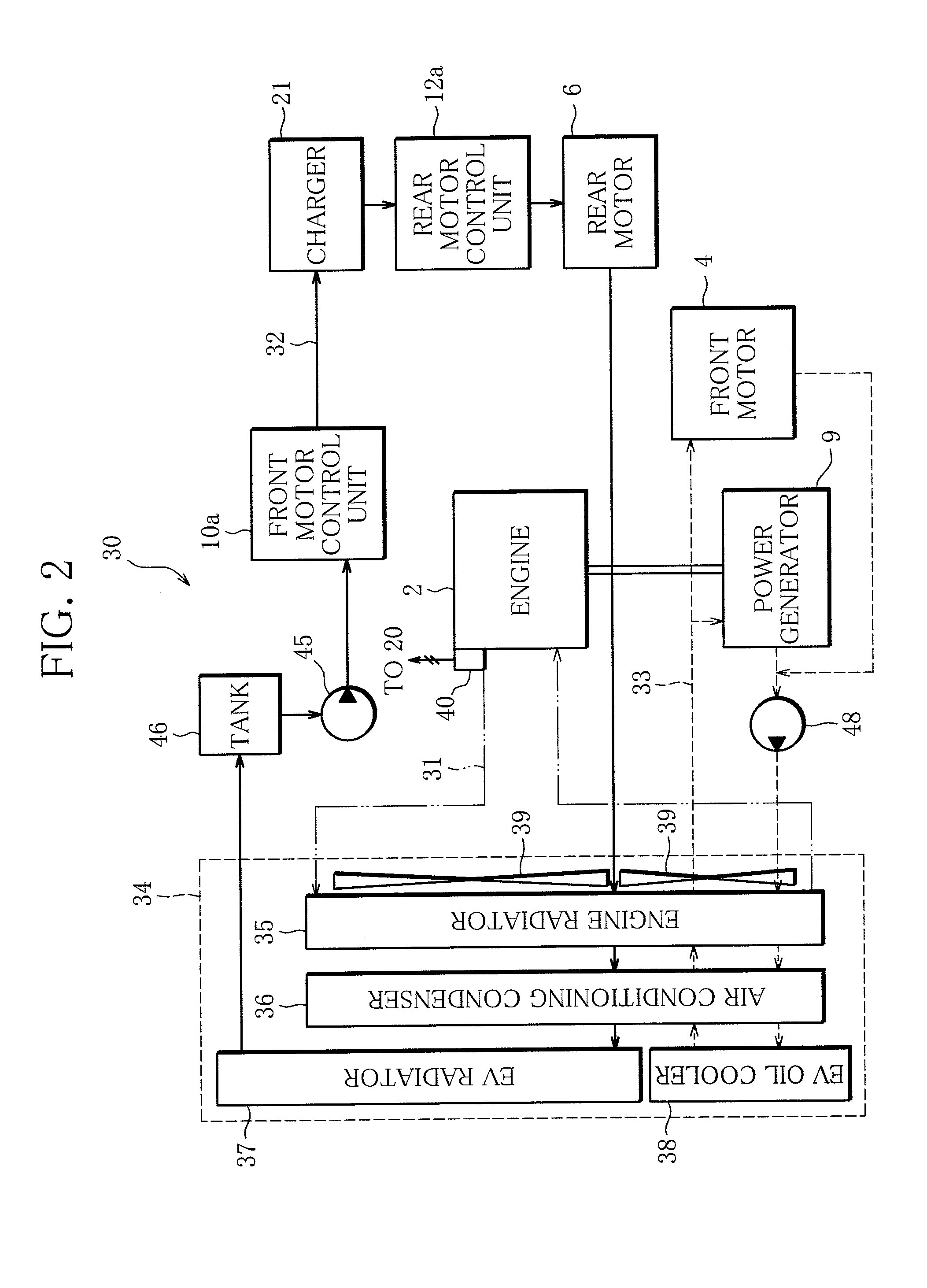
However, if the hybrid vehicle including the cooling system for the electric instrument as described above further allows a forced power generation mode, performing the forced power generation mode increases a load on the engine to increase a temperature of the cooling water, which may make it difficult to cool the engine itself, and further cool the electric instrument such as an inverter using the cooling system.

Method used


Image

  • Charge control device for hybrid vehicle
  • Charge control device for hybrid vehicle
  • Charge control device for hybrid vehicle

Examples


Embodiment Construction

[0016]Now, an embodiment of the present invention will be described with reference to the drawings.

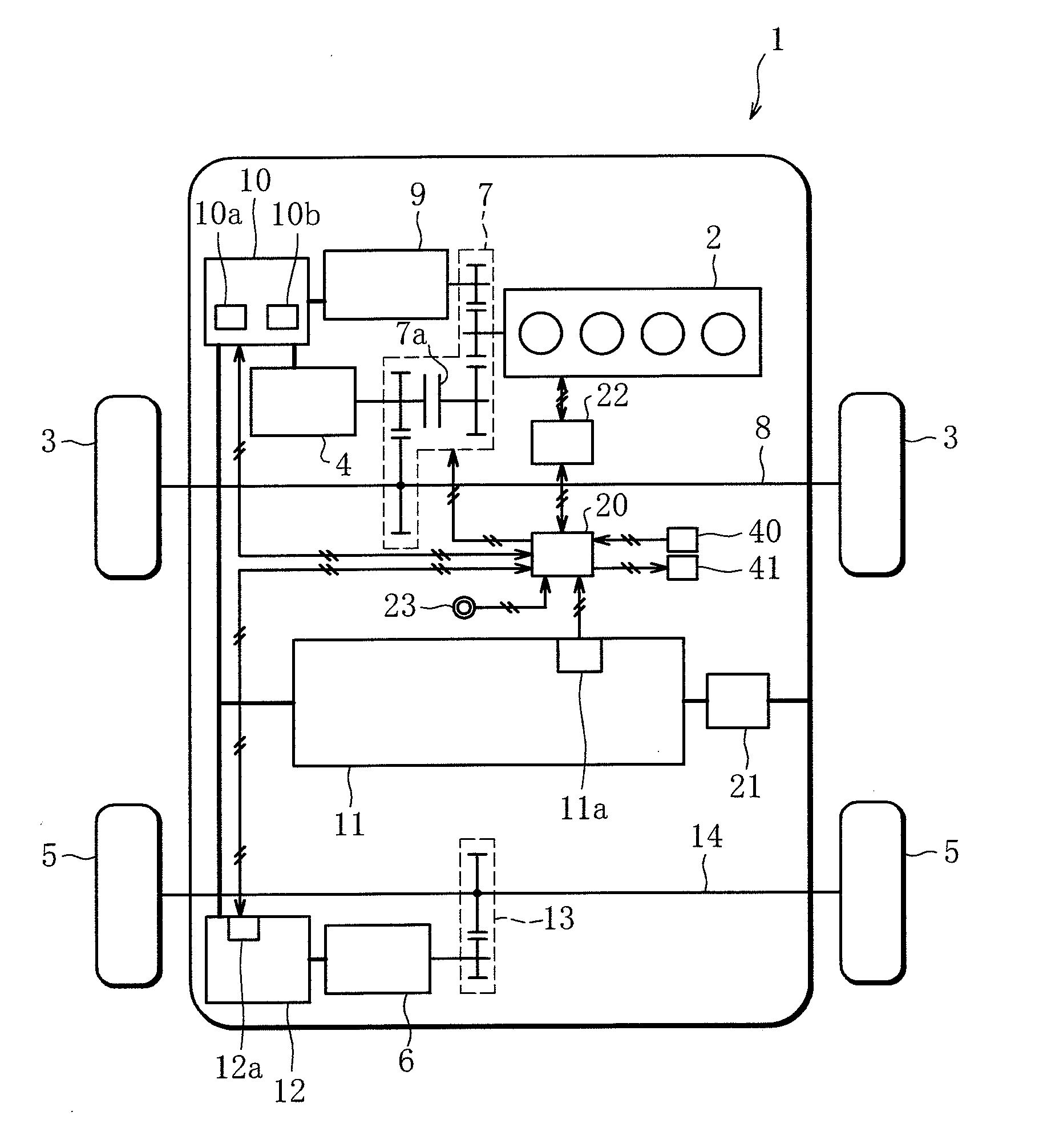
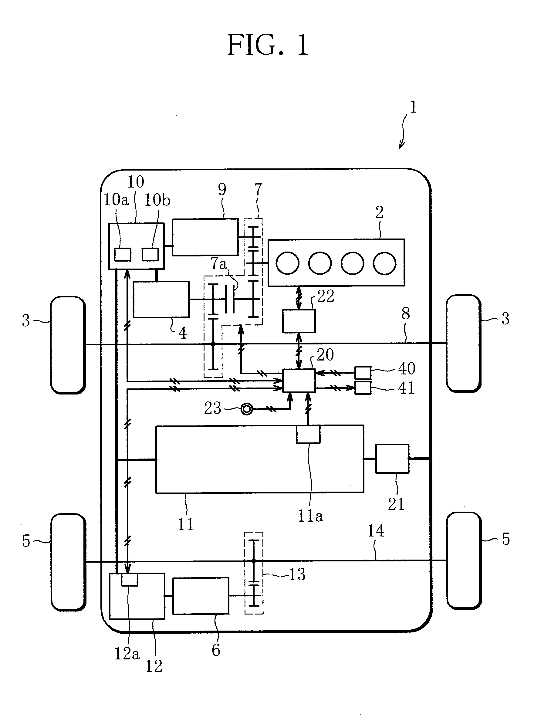
[0017]FIG. 1 is a schematic diagram of a plug-in hybrid vehicle (hereinafter referred to as vehicle 1) according to an embodiment of the present invention.

[0018]As shown in FIG. 1, the vehicle 1 of this embodiment is a four-wheel-drive vehicle that can travel by driving front wheels 3 using an output of an engine 2, and includes an electric front motor 4 (driving motor) that drives the front wheels 3, and an electric rear motor 6 (driving motor) that drives rear wheels 5.

[0019]The engine 2 can drive a drive axle 8 of the front wheels 3 via a reducer 7, and drive a power generator 9 via the reducer 7 to generate electric power.

[0020]The front motor 4 is driven by electric power of a high voltage supplied from a driving battery 11 and the power generator 9 included in the vehicle 1 via a front inverter 10, to drive the drive axle 8 of the front wheels 3 via the reducer 7. The reducer 7 i...


PUM


Abstract

A charge control device for a hybrid vehicle includes a driving battery supplying electric power to front and rear motors. It can switch between a normal power generation mode in which an engine is driven at a first rotational speed higher than an idling speed to generate electric power and charge the driving battery to a predetermined amount of charge, and a forced power generation mode in which the engine is forcedly driven at the first rotational speed or higher to generate electric power and charge the battery so as to maintain a higher amount of charge of the driving battery than a predetermined amount of charge, and drives the engine at an idling speed or lower to reduce an amount of electric power generation if the cooling water of the engine is a first predetermined temperature or higher when the forced power generation mode is performed.

Description

BACKGROUND OF THE INVENTION[0001]1. Field of the Invention[0002]The present invention relates to a charge control technique for a battery of a hybrid vehicle.[0003]2. Description of the Related Art[0004]A vehicle such as a hybrid vehicle including an engine, a travel driving motor, and a driving battery can use a power generator driven by the engine to charge the driving battery. Such a hybrid vehicle allows a normal power generation mode in which, for example, when a state of charge of the driving battery decreases, the engine is automatically actuated to charge the driving battery.[0005]Further, a vehicle has been also developed that allows a forced power generation mode in which an engine is forcedly actuated by an occupant operating a switch or the like to generate electric power until a driving battery is almost fully charged.[0006]Also, many hybrid vehicles include a cooling system that cools electric instruments such as a power generator, a travel driving motor, and an invert...

Claims


Application Information

Patent Timeline
Patent Type & Authority Applications(United States)
IPC IPC(8): B60W20/00B60L11/18B60L50/15B60L50/16
CPCB60L11/1809B60W20/10B60L2240/445B60L2240/545B60L2240/80B60L2250/16B60L2260/22B60L2260/26B60L2260/28B60K6/52B60W2510/0676B60W2710/244B60W20/13B60L50/62B60L50/16B60L58/12B60W10/06Y02T10/62Y02T10/70Y02T10/7072Y02T10/64
Inventor SETO, HIROKITOMITA, SHINSAKUSUZUKI, HIROYUKI
Owner MITSUBISHI MOTORS CORP
Learn More