
Shielding material used for shielding of radiation and method for shielding a radiation emitted from earth surface using the shielding material

Inactive Publication Date: 2014-06-19
SUURIE
View PDF5 Cites 17 Cited by
  • Summary
  • Abstract
  • Description
  • Claims
  • Application Information

AI Technical Summary

Benefits of technology

The patent text describes a rubber sheet made of natural or synthetic rubber that can be used as a shield to reduce the amount of radiation (such as beta rays and gamma rays) emitted from the surface of living space that is contaminated with a radioactive substance. The rubber sheet does not contain any vulcanizing agent and can be placed between two sheets of rubber or with other substances like sand iron, barium sulfonate, or zeolite. This invention helps to protect against excessive radiation and promote safety in living spaces.

Problems solved by technology

For such a case that an earth surface as living space has been contaminated with radioactive atoms or molecules, there is currently no technical information on the way to shield the beta rays and gamma rays emitted form the atoms or molecules or to reduce the radiation doses thereof.
However, it is extremely difficult to find, in Japan, a place where the highly contaminated soil of earth surface can be stored for more than several tens of years.
Further, when the highly contaminated soil layer has a depth of several meters, it is impossible to find a place capable of storing such soil.
It is also difficult to consider an appropriate measure for the dent formed by removing the contaminated soil.
Therefore, the decontamination creates another problem of where the radioactive atom- or radioactive molecule-rich substance removed by the decontamination should be stored.
When the contaminated place is an earth surface, it is unrealistic to move a contamination-free soil to the place from other place and replace the contaminated soil with the contamination-free soil.
The problem is that there is no further destination of such stored soil.
It is extremely difficult to find a place capable of accepting such soil of high radiation dose.
It can be learned from the above-mentioned case of soil and weeds that the treatment of radioactive substance by movement has a big problem.
Further, such decontamination is impossible to conduct by each individual.
Moreover, it is easily thought that the place of such positional reversion becomes undetectable over a long time.
However, the laying on an earth surface (which is a living environment), of this lead which is designated by European Government as an environmental load substance of Restriction of Hazardous Substance (RoHS), is not recommendable, in view of the toxicity of heavy metal.
The iron sheet is certainly a safe material; however, in assuming that the period of shielding is several tens of years or more than 100 years, there is no answer for prevention of buried iron sheet from rusting and resulting destruction.
Large-scale adoption of iron sheet as a shielding material for the earth surface of living space is not worth investigation, in view of iron as a resource or of industrial production steps of iron.
If a large layer of concrete is formed underground as a shielding material for the contaminated earth surface of living space, there arises a serious problem.
That is, when the underground need be dug later, it is difficult to destroy the concrete layer.
This difficulty applies also to the case of using an iron sheet.
For shielding the radiation emitted from the earth surface of living space or for treating the soil of high radiation dose, there is no acceptable answer with conventional techniques.
Since there is no experience of treatment of the contamination of living space, there is no sufficient answer with conventional techniques.

Method used


Image

  • Shielding material used for shielding of radiation and method for shielding a radiation emitted from earth surface using the shielding material
  • Shielding material used for shielding of radiation and method for shielding a radiation emitted from earth surface using the shielding material

Examples


example 1

Comparative Examples 1 and 2

[0072]100 parts by weight of butyl rubber and 250 parts by weight of barite were compounded using an open roll to produce a rubber sheet of 18 mm in thickness as a shielding material. In Example 1, this sheet was placed on the earth surface of measurement site and a measurement was made thereon. In Comparative Example 1, a measurement was conducted at the same position as in Example 1 without using the rubber sheet. In Comparative Example 2, a measurement was conducted in other measurement site of different radiation dose without using the rubber sheet, for comparison.

TABLE 1-1Formulation of rubber sheetButyl 268 (1)100 parts by weightBarite (2)250 parts by weight

TABLE 1-2ComparativeComparativeExample 1Example 1Example 2(4)(5)(6)Measured radiation85~109201~2430~12dose (3)(unit: CPM)

Notes

[0073](1) Butyl 268 produced by Japan Butyl Co., Ltd.[0074](2) Barite BC produced by Sakai Chemical Industry Co., Ltd.[0075](3) A value obtained by subtracting 50 CPM (bac...

example 2

Comparative Example 3

[0082]70 parts by weight of butyl rubber, 30 parts by weight of EPDM and 200 parts by weight of sand iron were compounded using an open roll to produce a rubber sheet (the formulation is shown in Table 2-1) of 16 mm in thickness as a shielding material. In Example 2, this sheet was placed on the earth surface of measurement site and a measurement was made thereon. In Comparative Example 3, a measurement was conducted at the same position as in Example 2, using no rubber sheet.

TABLE 2-1Formulation of rubber sheetButyl 268 (1)70 parts by weightEP 33 (2)30 parts by weightSand iron (3)200 parts by weight 

TABLE 2-2Example 2Comparative(5)Example 3 (6)Measured radiation98~119153~208dose (4)(unit: CPM)

Notes

[0083](1) Same as (1) of Example 1[0084](2) An ethylene-propylene rubber containing ethylidene norbornene as a diene component and having an iodine value of 26.0, produced by Japan Synthetic Rubber Co., Ltd.[0085](3) A sand iron for experiment, marketed by Kajidai Tek...

examples 4 and 5

Comparative Example 5

[0101]A formulation of Table 4-1 was compounded using an open roll to produce a rubber sheet of 9 mm in thickness. Sand iron or barite was placed in a thickness of 18 mm, as an intermediate material, between two of the produced rubbers. In Examples 4 and 5, this combined shielding material was placed on an earth surface and a radiation dose was measured thereon. In Comparative Example 5, the measurement of radiation dose was made without using the combined shielding material. The results are shown in Table 4-3.

TABLE 4-1Formulation of rubber sheetButyl 268 (1)100 parts by weightBarite (2) 30 parts by weightHYK talc (3)100 parts by weightCalcium bicarbonate (4) 70 parts by weight

TABLE 4-2Intermediate material placed between two rubber sheetsExample 4Example 5Sand iron (5)——Barite (2)

TABLE 4-3ComparativeExample 4Example 5Example 5Measured radiation91~134102~124462~480dose (6)(unit: CPM)

Notes

[0102](1) and (2) Same as (1) and (2) in Example 1[0103](3) HYK talc of Fuj...


PUM

PropertyMeasurementUnit
Fractionaaaaaaaaaa
Percent by massaaaaaaaaaa

Abstract

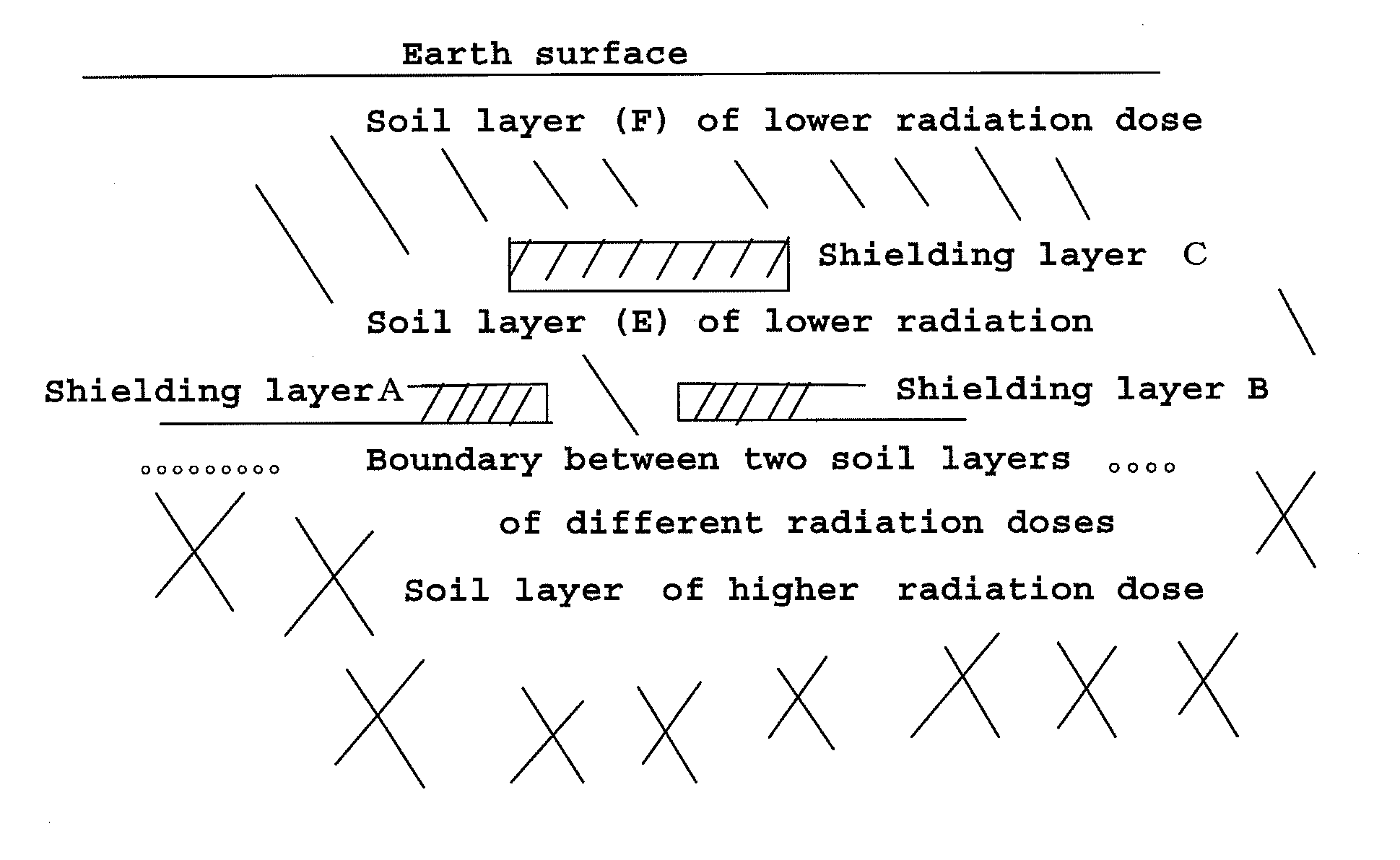
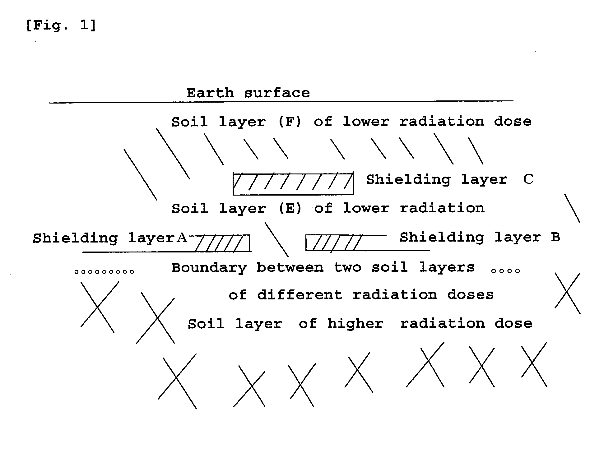
In the present invention, there is provided, as a shielding material for beta rays or gamma rays emitted from an earth surface surrounding a nuclear power plant after an accident, a rubber sheet wherein a synthetic rubber or natural rubber, each containing no vulcanizing agent is compounded with a large amount of sand iron or barite. By placing this shielding material on a radiation-contaminated earth surface, or by reversing the position of the soil of earth surface of higher radiation dose and the position of the soil beneath the earth surface, of lower radiation dose, in such a way that the above-mentioned shielding material is placed between the new upper-position soil of lower radiation dose and the new lower-position soil of higher radiation dose, the dose of radiation emitted from the earth surface can be reduced.

Description

BACKGROUND OF THE INVENTION[0001]1. Field of the Invention[0002]The present invention relates to a shielding material which is a rubber composition obtained by kneading or mixing natural rubber, a synthetic rubber or a mixture thereof with one member selected from sand iron, barium sulfate and zeolite, or a mixture thereof (the rubber composition contains neither vulcanizing agent nor vulcanization accelerator) and which is to be laid on the earth surface contaminated with a radioactive substance, to reduce the dose of radiation emitted from the earth surface.[0003]The present invention also relates to a method for reducing the dose of radiation (beta rays and gamma rays) emitted from the earth surface contaminated with a radioactive substance, by reversing the position of the earth surface layer (soil and / or dead leaf) of higher radiation dose and the position of a layer beneath the earth surface layer, of lower radiation dose and placing, between the two layers, a rubber sheet (wh...

Claims


Application Information

Patent Timeline
IPC IPC(8): G21F1/00
CPCG21F1/00B09B1/004E02D31/006G21F1/10G21F9/36Y02W30/30
Inventor ONIZAWA, MASAO
Owner SUURIE
Learn More