
Three-Element Antenna Array for Wireless Handsets

a wireless handset and antenna array technology, applied in the direction of antennas, electrical equipment, etc., can solve the problems of simultaneous power increase and interference minimization of as little as three antenna elements, and achieve the effects of low memory requirements, high signal clarity, and fast processing

Inactive Publication Date: 2016-09-15
BOARD OF TRUSTEES OPERATING MICHIGAN STATE UNIV
View PDF4 Cites 9 Cited by
  • Summary
  • Abstract
  • Description
  • Claims
  • Application Information

AI Technical Summary

Benefits of technology

This patent describes a technique that allows for simultaneous improvement of signal quality and reduction of unwanted signals in a mobile device. This is done by using a special processor to maximize the desired signal and cancel out interferers. This results in higher signal clarity and less noise, improving the overall performance of the mobile device's antenna.

Problems solved by technology

With the present techniques, however, simultaneous power increase and interference minimization can occur with as little as three antenna elements.

Method used


Image

  • Three-Element Antenna Array for Wireless Handsets
  • Three-Element Antenna Array for Wireless Handsets
  • Three-Element Antenna Array for Wireless Handsets

Examples


Embodiment Construction

[0019]Although the following text sets forth a detailed description of numerous different embodiments, it should be understood that the legal scope of the description is defined by the words of the claims set forth at the end of this patent and equivalents. The detailed description is to be construed as providing examples only and does not describe every possible embodiment since describing every possible embodiment would be impractical. Numerous alternative embodiments could be implemented, using either current technology or technology developed after the filing date of this patent, which would still fall within the scope of the claims.

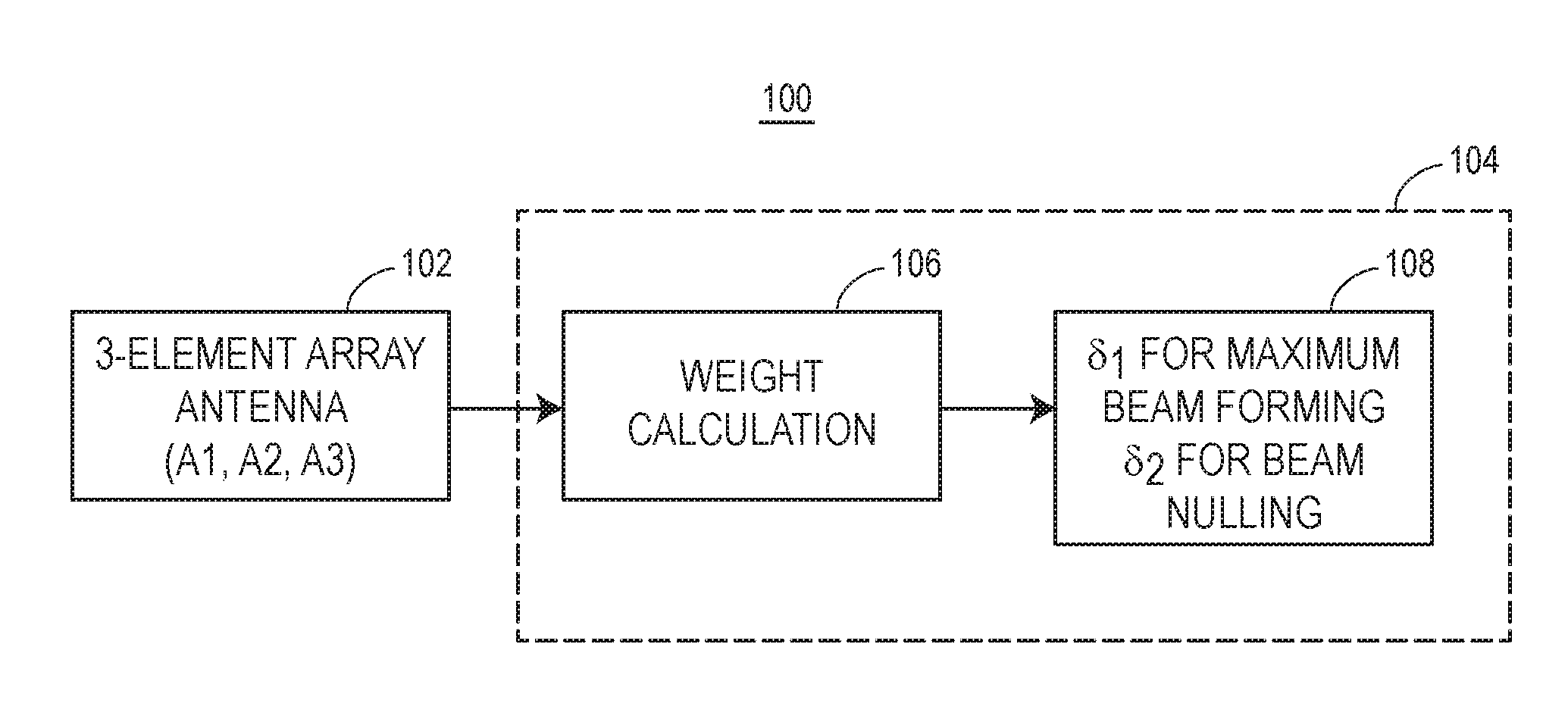
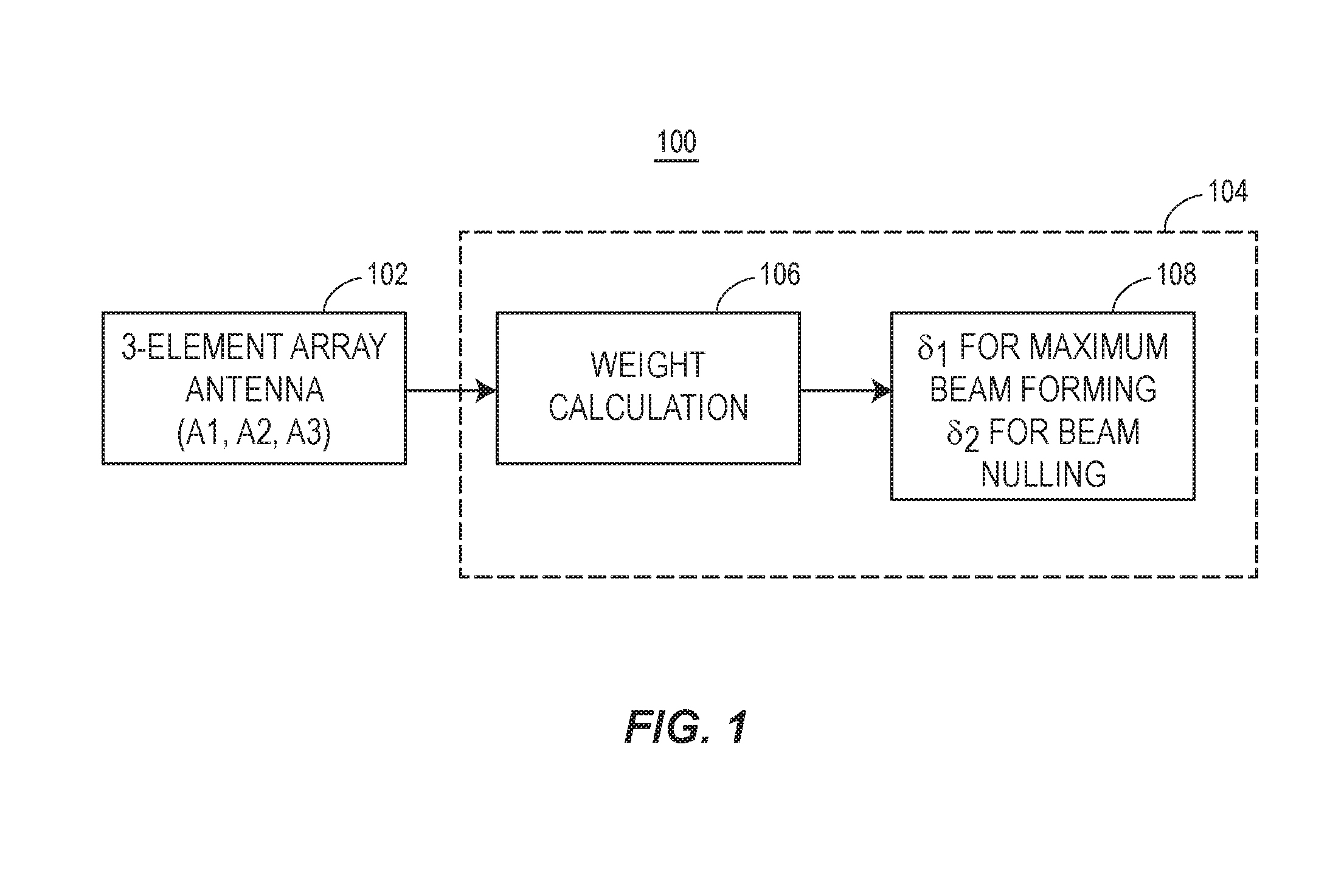
[0020]A mobile station beam-forming processor makes use of the estimation of the position of the mobile station (with respect to a base station). That estimation may include known techniques to determine the position or angle of arrival (AoA). With this information known, the mobile station processor coupled to the multiple array antenna system herei...


PUM


Abstract

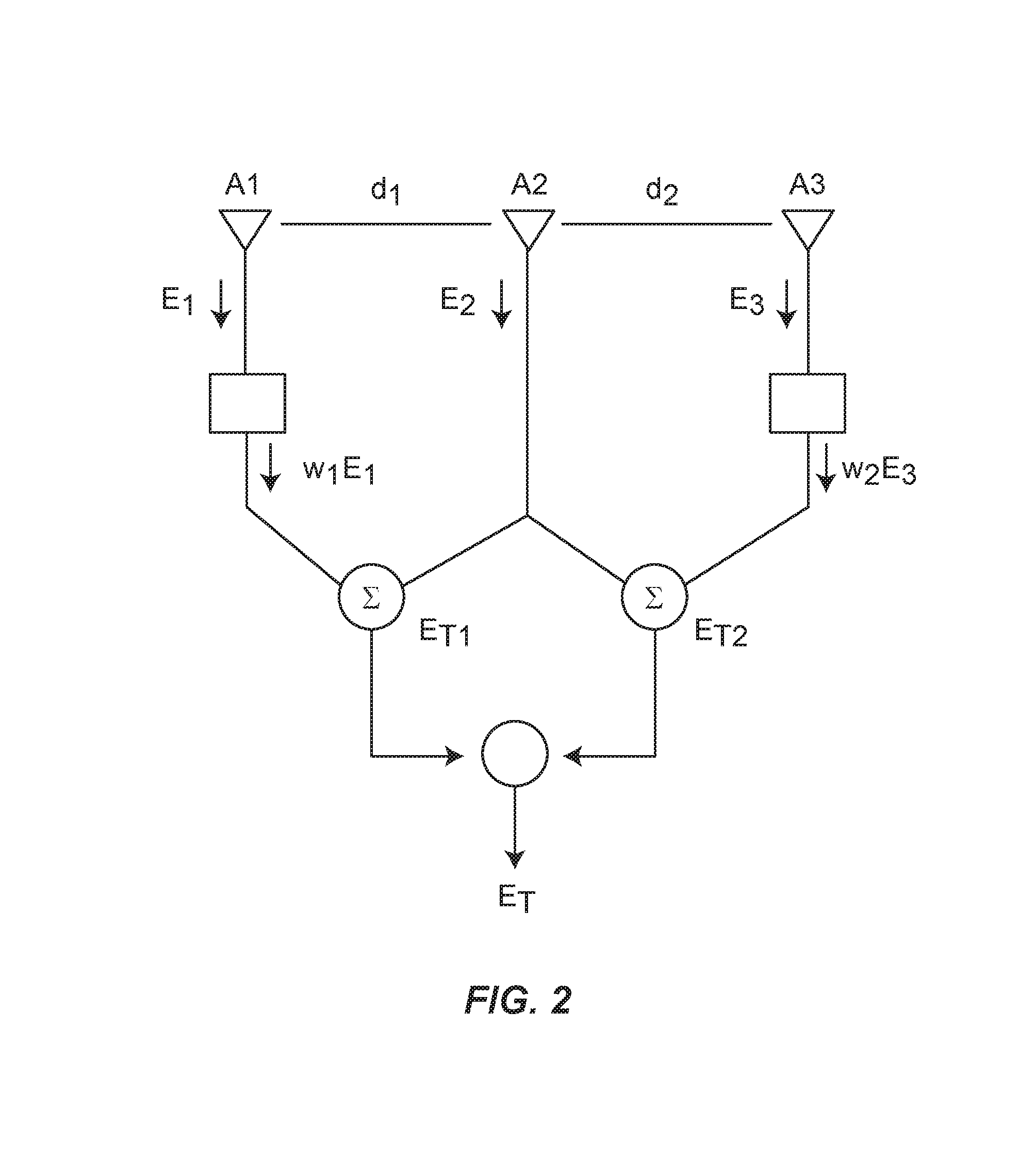
A multiple antenna beam steering device includes three-element array, which are controlled to increase power reception in the direction of the desired signal while simultaneously minimizing signal reception in one or more directions of interference, using selective weighting of received signals, and specified summation stages to produce combined array factors that are used to form a beam pattern that is both maximized in at least one signal direction and minimized in at least one interference direction.

Description

CROSS-REFERENCE TO RELATED APPLICATION[0001]This application claims the benefit of U.S. Application Ser. No. 62 / 130,993, filed Mar. 10, 2015, entitled “Three-Element Antenna Array for Wireless Handsets,” which is hereby incorporated by reference in its entirety.BACKGROUND[0002]The background description provided herein is for the purpose of generally presenting the context of the disclosure. Work of the presently named inventors, to the extent it is described in this background section, as well as aspects of the description that may not otherwise qualify as prior art at the time of filing, are neither expressly nor impliedly admitted as prior art against the present disclosure.[0003]Antenna beam-forming is largely confined to stationary base stations. Current beam-forming techniques combine the electromagnetic signals of array antenna elements to form a desired output. The array antenna behaves like a space domain filter, whereby interference signals that are being transmitted and / o...

Claims


Application Information

Patent Timeline
Patent Type & Authority Applications(United States)
IPC IPC(8): H01Q3/26H01Q3/36
CPCH01Q3/36H01Q3/2611H01Q3/2605H01Q3/30
Inventor HOOLE, S. RATNAJEEVAN H.HOOLE, PAUL
Owner BOARD OF TRUSTEES OPERATING MICHIGAN STATE UNIV
Learn More