
Managing Electrical Power for a Nuclear Reactor System

a nuclear reactor and electrical power technology, applied in nuclear engineering, emergency power supply arrangements, greenhouse gas reduction, etc., can solve the problems of affecting the commercial affecting the design and operation of electrical power systems, and affecting the economic viability of nuclear power plants, so as to reduce the cost of maintenance and storage, and reduce the cost of such qualified 1e batteries. , the effect of reducing the space requirements

Active Publication Date: 2014-06-05
NUSCALE
View PDF9 Cites 14 Cited by
  • Summary
  • Abstract
  • Description
  • Claims
  • Application Information

AI Technical Summary

Benefits of technology

The present invention relates to an improved electrical power system for nuclear reactor systems. The system reduces maintenance costs associated with battery replacement, reduces space requirements by eliminating certain components, and alleviates the risk of core damage in the event of a power loss. The system also includes redundant schemes for each shared AC bus, supports a passive nuclear reactor system, and simplifies operation action and maintenance. Furthermore, the system minimizes the number of battery cells used and supports a station blackout coping.

Problems solved by technology

Further, there may be constraints on the type and construction of power sources, such as batteries used as power sources.
Further, the design and construction of particular nuclear reactor designs may also constrain the design and operation of the electrical power system.
Further, commercial viability of a nuclear power plant may be impacted due to significant capital and operation and maintenance costs associated with the electrical power sources and infrastructure that supports the sources.
Also, in some modular nuclear reactor systems that use passive cooling, all safety function structures, systems, and components (SSC) may fail to their safe state upon loss of all AC and DC power without adverse impact to the nuclear power system.

Method used


Image

  • Managing Electrical Power for a Nuclear Reactor System
  • Managing Electrical Power for a Nuclear Reactor System
  • Managing Electrical Power for a Nuclear Reactor System

Examples


Embodiment Construction

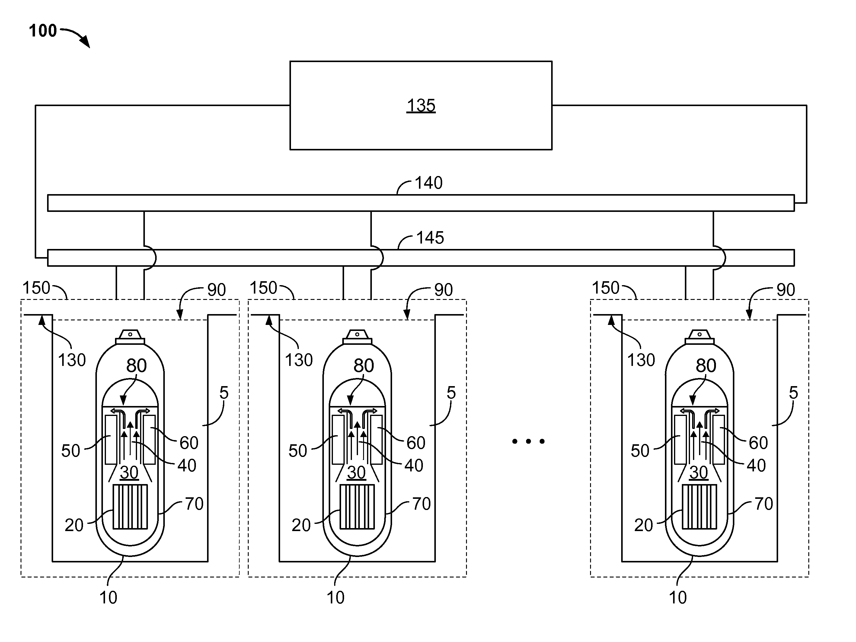
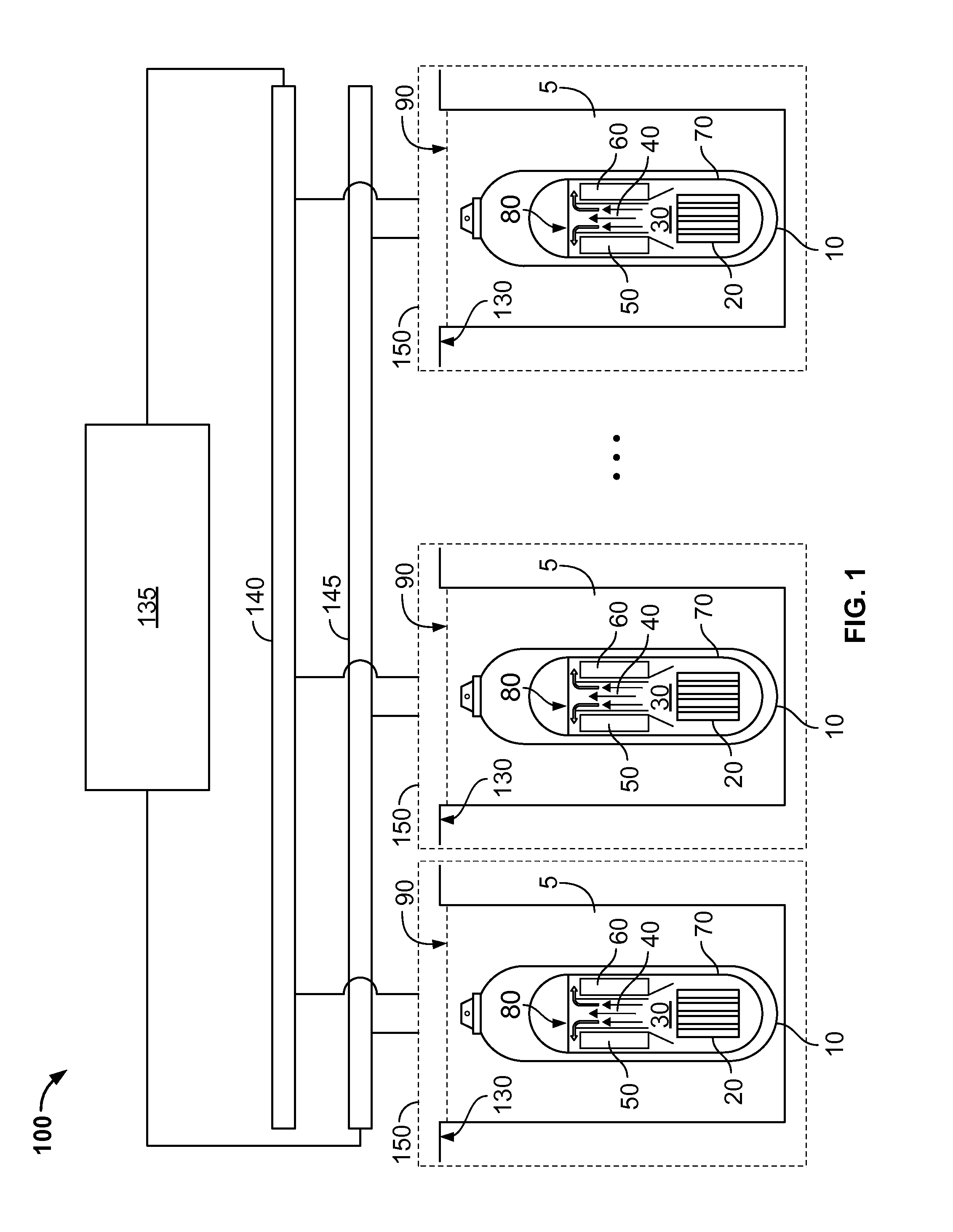
[0042]FIG. 1 illustrates an example implementation of a nuclear power system 100 that includes multiple nuclear reactor systems 150 and an electrical power distribution system. In some implementations, the system 100 may provide for an electrical power distribution system that is operable to supply electrical power to critical systems (e.g., one or more engineered safety feature (ESF) electrical loads) backed by a non-qualified battery system (e.g., VRLA type batteries) while also supply electrical power to non-critical systems (e.g., active post-accident monitoring (PAM) loads and common loads in the nuclear power system 100) backed by a qualified battery system (e.g., VLA type batteries). In some implementations, the ESF loads may be designed to fail, e.g., upon loss of main AC power, to their respective safe positions. Further, in some implementations, ESF loads may share a main bus and a back-up (or redundant) bus. The main bus and back-up bus may both be supported (e.g., electr...


PUM


Abstract

An electrical power system for a nuclear power facility includes an active alternating current (AC) power bus configured to be electrically coupled to a plurality of engineered safety feature (ESF) loads of a plurality of nuclear power systems, each of the ESF loads configured to fail to a safe position upon loss of primary AC power; a critical battery system electrically coupled to the active AC bus, the critical battery system comprising a plurality of valve regulated lead acid (VRLA) batteries; and a primary AC power source electrically coupled to the active AC bus.

Description

CROSS-REFERENCE TO RELATED APPLICATIONS[0001]This application claims priority to U.S. Provisional Patent Application Ser. No. 61 / 733,258, filed on Dec. 4, 2012, entitled “Managing Electrical Power for a Nuclear Reactor System,” the entire contents of which are incorporated herein by reference in their entirety.TECHNICAL BACKGROUND[0002]This disclosure describes an electrical power system for a nuclear reactor system.BACKGROUND[0003]Electrical power systems for nuclear reactor systems may be designed and operate under a variety of constraints. For example, there may be regulatory requirements associated with safety related power systems, such as direct current (DC) powered systems. Further, there may be constraints on the type and construction of power sources, such as batteries used as power sources. For instance, only certain battery-types may be “qualified” (e.g., meet regulatory requirements such as those that define a “1E” scheme under IEEE Std 308-2001, section 3.7, endorsed by...

Claims


Application Information

Patent Timeline
Patent Type & Authority Applications(United States)
IPC IPC(8): H02J3/00
CPCH02J3/005G21D1/00G21D3/04H02J9/062H02J2310/18Y02E30/00H02J9/06H02J3/0073Y02E30/30Y04S10/52
Inventor HOUGH, TED
Owner NUSCALE
Learn More