
Multifunctional guidewire assemblies and system for analyzing anatomical and functional parameters

a multi-functional, guidewire technology, applied in the field of multi-functional guidewire assemblies and system for analyzing anatomical and functional parameters, can solve the problems of increasing the time and complexity of the procedure, inconvenient for patients, and high cost of methods

Inactive Publication Date: 2014-05-22
ANGIOMETRIX CORP
View PDF8 Cites 111 Cited by
  • Summary
  • Abstract
  • Description
  • Claims
  • Application Information

AI Technical Summary

Benefits of technology

The patent describes a guidewire assembly that has a pressure sensor and a processor located within the guidewire. This reduces the number of conductors required and noise that may occur if a processor is located externally. The pressure sensor has a diaphragm and a substrate with conductive wires insulated from the diaphragm. The wires are soldered to the substrate and connected to termination pads on the substrate. A processor can be placed within the guidewire, eliminating the need for wires or leads. The guidewire assembly can also have a wireless transmitter to transmit sensed information without the need for wires or wires from an external source. This eliminates the need for leads or wires and provides a more efficient and safe way to use a guidewire assembly in medical procedures.

Problems solved by technology

These methods, however, are either very expensive and / or are cumbersome.
In addition to the costs and time disadvantages, these procedures are also inconvenient to the patient.
Since both the measurement device and the dilatation catheter can be difficult to advance to the obstructed site, multiple device exchanges have to be made adding more time and complexity to the procedure.
The technique requires injection of fluid into the expander with known concentration at the time of making the measurements using the electrodes, thus adding to the complexity of the procedure.
The repeatability of measurements may be affected if the injected fluid does not clear out the blood completely in the vessel at the time of the measurements.
Additionally, typical imaging techniques provide very limited information, especially about blood vessels and the heart.
This can lead to inaccurate placements and hence less than ideal treatment.
Further, in some instances, to obtain lumen trajectory in a 3D volume, complete procedural changes may be necessary, which may not be conducive for adaptation with existing techniques.
Also, the imaging procedures described may be cumbersome and complex, and consequently, the medical procedure requires modification to accommodate the imaging procedure, which sometimes is impractical.
However, none of these applications address the co-registering of parametric information with the positional information of the endo-lumen instruments.
The technique described herein presents complexity in terms of first having a 3D map of a region of interest, then obtaining 3D image of region of interest, then segmenting the 3D image to obtain a 3D profile of region of interest and then superimposing on the 3D map.
The technique is complex and uses threshold value to provide some regulation data for catheter guidance.
The technique, however, fails to co-register the parametric information with the positional information for accurate guidance for medical procedures.
Mapping on a pre-selected model can lead to errors as the heart is in dynamic motion at any given time and the model may not represent the current state for the images heart
Another possibility is that the micro-vasculature itself is diseased and hence is the more significant bottleneck to blood flow.
Further, in an extreme case, the relevant portion of the myocardium may have become dysfunctional and has a significant low physiologic flow need.
However, it is well established that such a treatment does not result in clinical benefits for a functionally non-significant lesion.
To achieve an optimal therapy the physician thus may have to go through multiple product exchanges which is cumbersome, expensive, and presents added procedure time and risk to the patients.
However, because guidewires typically have a relatively small diameter, e.g., 0.014 in. diameter, there are significant challenges due to limited space.
Since the pressure sensor is integrated into a 0.014 in. diameter guidewire, using multiple lead wires that run through the entire length of the guidewire present assembly challenges due to limited real estate.
Furthermore, the elongate wires may also act as antennas and are susceptible to cross-talk and noise infiltration.
Moreover, in the event that additional components are placed within or along the guidewire, additional circuitry or components may further complicate guidewire assembly and increase the possibility of cross-talk and noise in the pressure sensing signals.
The effects of a parasitic network may be time varying due to temperature changes and physical changes arising from the mechanical stresses on the device that makes accurate compensation fairly challenging.
As a result, accuracy of pressure measurements may suffer or the device may need cumbersome calibration tests.
However, the situation becomes more complex if there are multiple stenoses in the network of blood vessels, some of which could be on the same artery, and some could be in a branch downstream.
In such a case, it is not easy to determine the treatment plan and the determination of functionally significant lesions that are indicated for treatment is less obvious in several cases.
The FFR for the stenosis alone may not be appropriate for determining functional significance.
The situation gets more complicated when there are branches and collaterals that have multiple stenosis of varying degrees.
Other than being sub-optimal, this approach is also cumbersome since it may require multiple iterations of diagnosis and treatment.
These are the current practical clinical challenges faced by clinicians of using an FFR measure to make treatment decisions in multiple serial and distributed lesions.

Method used


Image

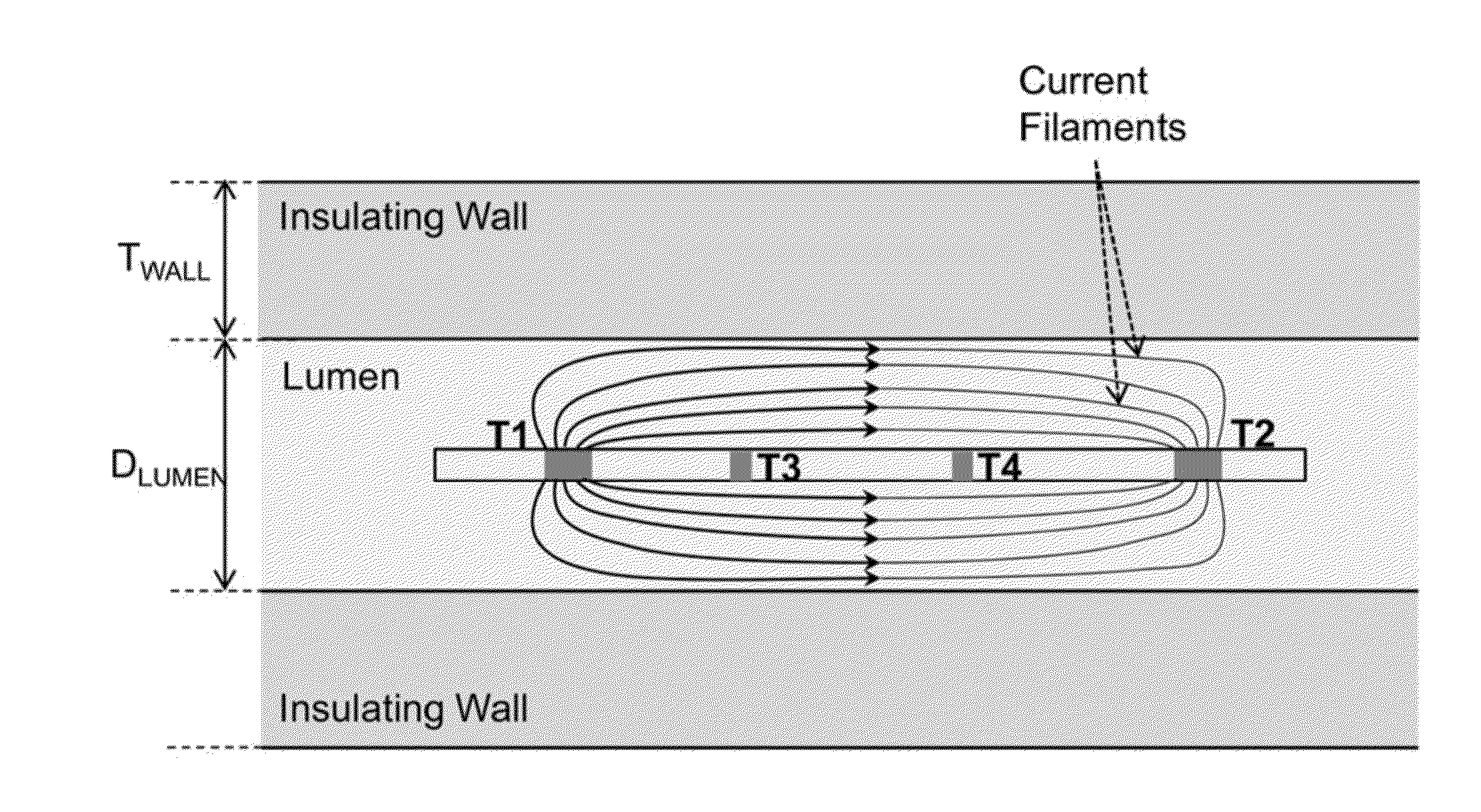
  • Multifunctional guidewire assemblies and system for analyzing anatomical and functional parameters
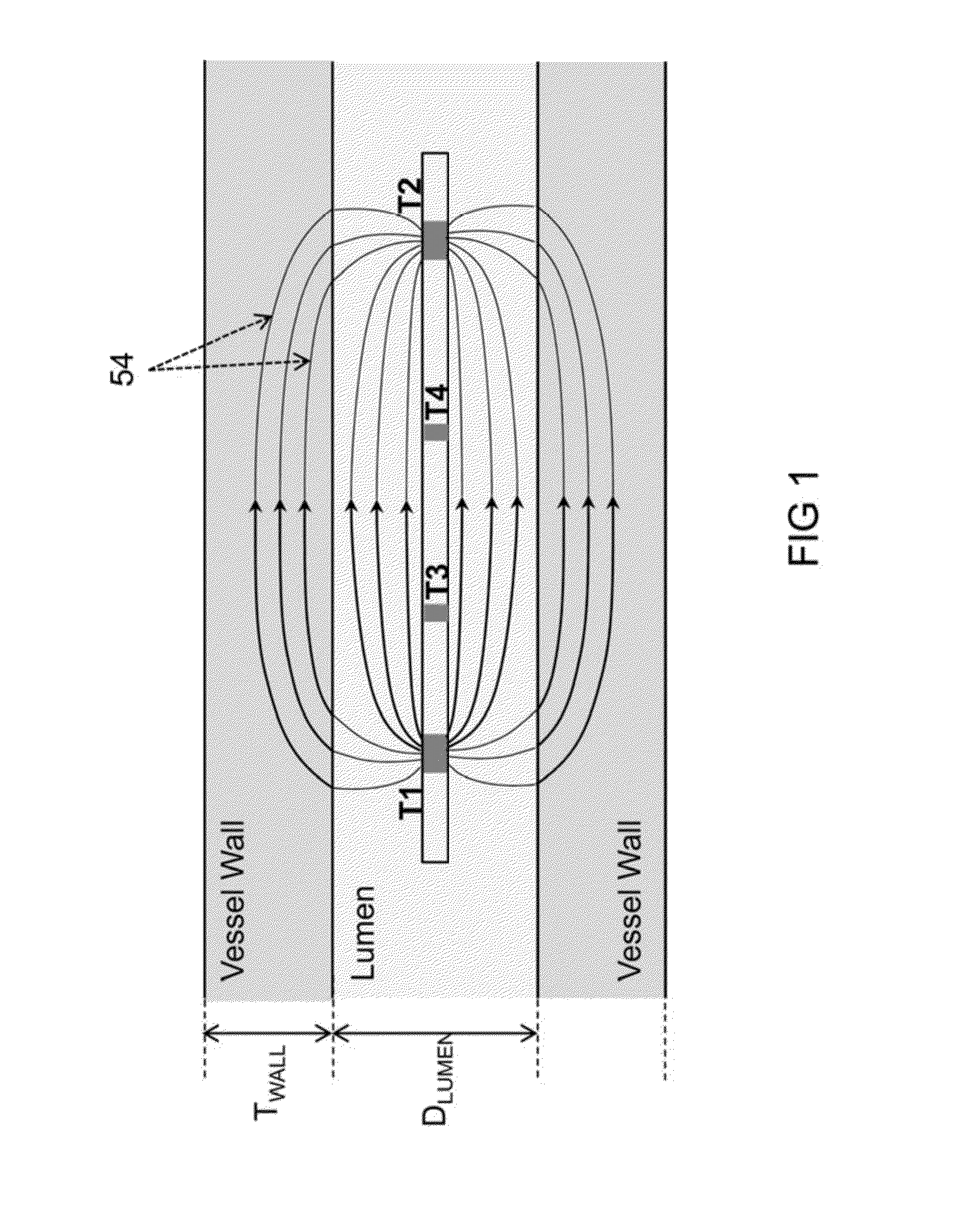
  • Multifunctional guidewire assemblies and system for analyzing anatomical and functional parameters
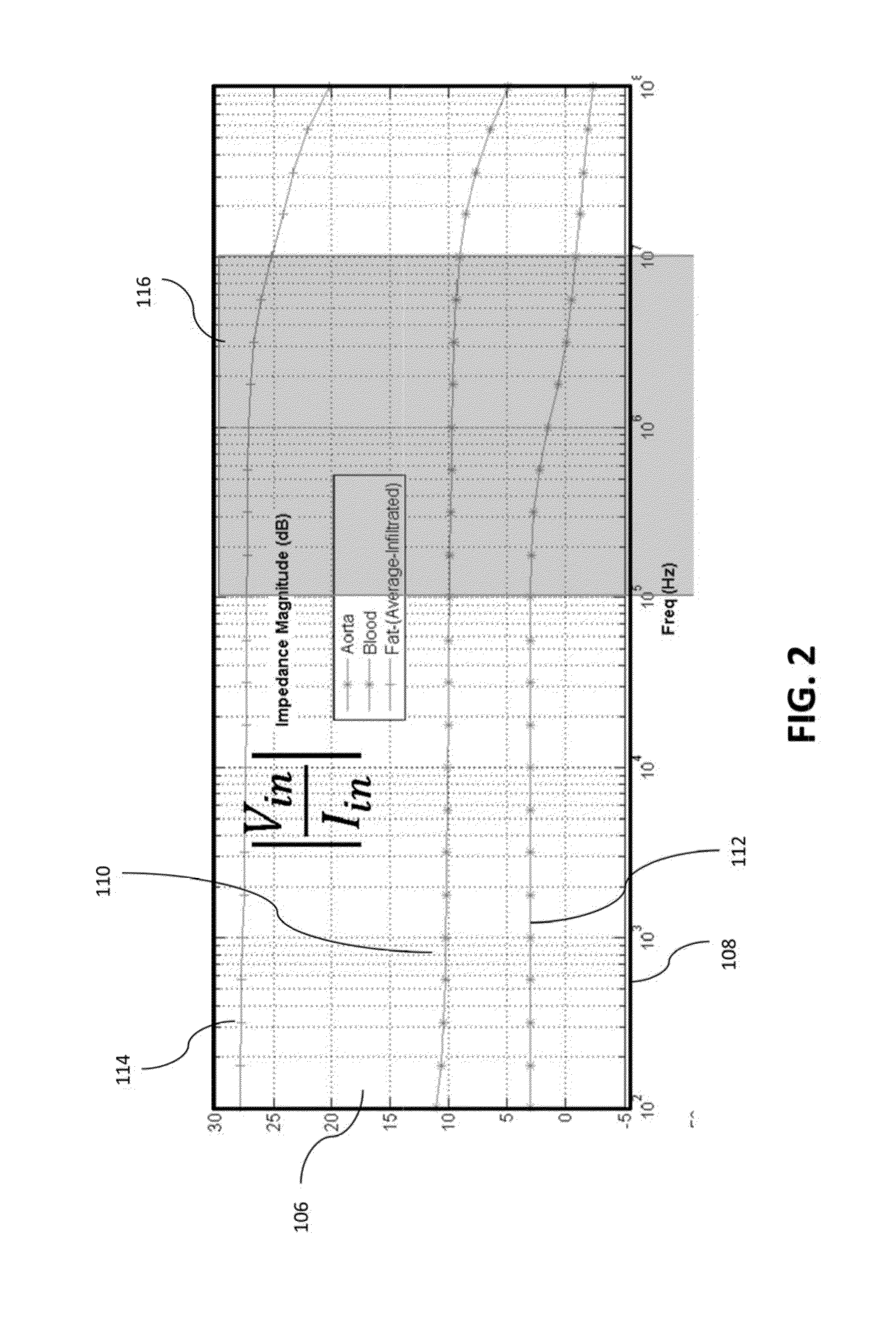
  • Multifunctional guidewire assemblies and system for analyzing anatomical and functional parameters

Examples


example 1

[0261]In an exemplary implementation, the excitation frequency band was chosen between 40 KHz (fL) to 10 MHz (fH) based on the electrical characteristics of blood, tissue and fats. A 16 bit D / A converter was chosen to operate at a sampling rate of fs (=20 MHz). The chosen D / A converter accepts offset binary sequence (0x0000 for the lowest value and 0xFFFF for the highest value). The Most Significant Byte of the converter is toggled according to the single bit pseudo random pattern, while the next bit was kept permanently at logic 1. All other bits were kept at logic 0. Hence the D / A input toggles between 0x4000 and 0xC000, depending on a 0 or a 1 from the pseudo random generator. The pseudo random generator resides on a back end entity and is comprised of a chain of 9 D-flipflops referred to as flops, to represent a 9-tap pseudo random sequence. The resultant sequence is a maximal length pseudo random sequence with length of L=511 (29−1). The generator polynomial used to generate th...

example 2

[0265]In yet another implementation, as shown in FIG. 15, an OFDM sequence is constructed using Nfreq (=256) discrete tones of equal amplitudes and each being at a random phase. The phase angles for each tone are adjusted so as to obtain the PAR lower than 1.4. The construction of the OFDM sequence can be done either simply by adding all the discrete tones together or, by performing a IFFT (Inverse Fast Fourier Transform) of a symmetric sequence of 2Nfreq (=512) complex numbers, where the first 256 complex numbers relate to the amplitude and phase of the individual tones and the next set of 256 complex numbers are simply the complex conjugate of the first 256 arranged in the reverse order (FIG. 15). The resultant time domain signal is shown in FIG. 16 that is sampled at fs (=20 MHz) which is twice the largest frequency of interest (fH). The lowest frequency in this sequence is fL (=fs / 2Nfreq=39.0625 KHz). The time domain OFDM sequence can also be produced at higher sampling rates us...


PUM


Abstract

Multifunctional guidewire assemblies and system for analyzing anatomical and functional parameters are described. Using a single guidewire assembly, functional and anatomical measurements and identification of lesions may be made. Functional measurements such as pressure may be obtained with a pressure sensor on the guidewire while anatomical measurements such as luminal dimensions may be obtained by utilizing an electrode assembly along the guidewire. The vascular network and stenosed lesions may be modeled into an equivalent electrical network and solved based on the measured parameters to obtain unknown parameters of the electrical network. Several treatment plan options may be constructed where each plan may correspond to the treatment of a subset of particular lesions. The anatomical outcome for each of the treatment plans may be estimated and the equivalent modified electrical parameters may be determined. Then, each of the electrical networks for each plan may be solved to determine the functional outcome for each treatment plan and the outcomes for all treatment plans may be presented to a physician.

Description

CROSS-REFERENCE TO RELATED APPLICATIONS[0001]This application is a continuation of International Pat. App. PCT / US2012 / 034557 filed Apr. 20, 2012, which is a continuation-in-part of U.S. patent application Ser. No. 13 / 305,630 filed Nov. 28, 2011, now U.S. Pat. No. 8,494,794, which itself is a continuation-in-part of U.S. patent application Ser. No. 13 / 159,298 filed Jun. 13, 2011 which claims the benefit of priority to U.S. Prov. Pat. App. 61 / 383,744 filed Sep. 17, 2010 and also claims the benefit of foreign priority to Indian Prov. Pat. App. 1636 / CHE / 2010 filed Jun. 13, 2010, each of which is incorporated herein by reference in its entirety.INCORPORATION BY REFERENCE[0002]All publications and patent applications mentioned in this specification are herein incorporated by reference to the same extent as if each individual publication or patent application was specifically and individually indicated to be incorporated by reference.TECHNICAL FIELD OF THE INVENTION[0003]The invention gene...

Claims


Application Information

Patent Timeline
IPC IPC(8): A61B5/0215A61B5/053
CPCA61B5/0538A61B5/0215A61B5/02007A61B5/064A61B5/6853A61B6/12A61B6/463A61B6/504A61B6/5241A61B6/5288A61B6/541A61B8/0841A61B8/0891A61B8/12A61B8/463A61B8/565A61B8/582A61M25/1018
Inventor PATIL, NITINSUBRAMANIYAN, RAGHAVANDUTTA, GOUTAM
Owner ANGIOMETRIX CORP
Learn More