Gas turbine combustor
a technology of combustor and gas turbine, which is applied in the direction of machines/engines, mechanical equipment, light and heating equipment, etc., can solve the problems of complicated and troublesome work, considerably time-consuming and costly, and the modification of the respective portion is far more complicated and troublesome, so as to achieve relatively short lift distance, relatively long lift distance, and relatively high flow velocity of the mixture
- Summary
- Abstract
- Description
- Claims
- Application Information
AI Technical Summary
Benefits of technology
Problems solved by technology
Method used
Image
Examples
first embodiment
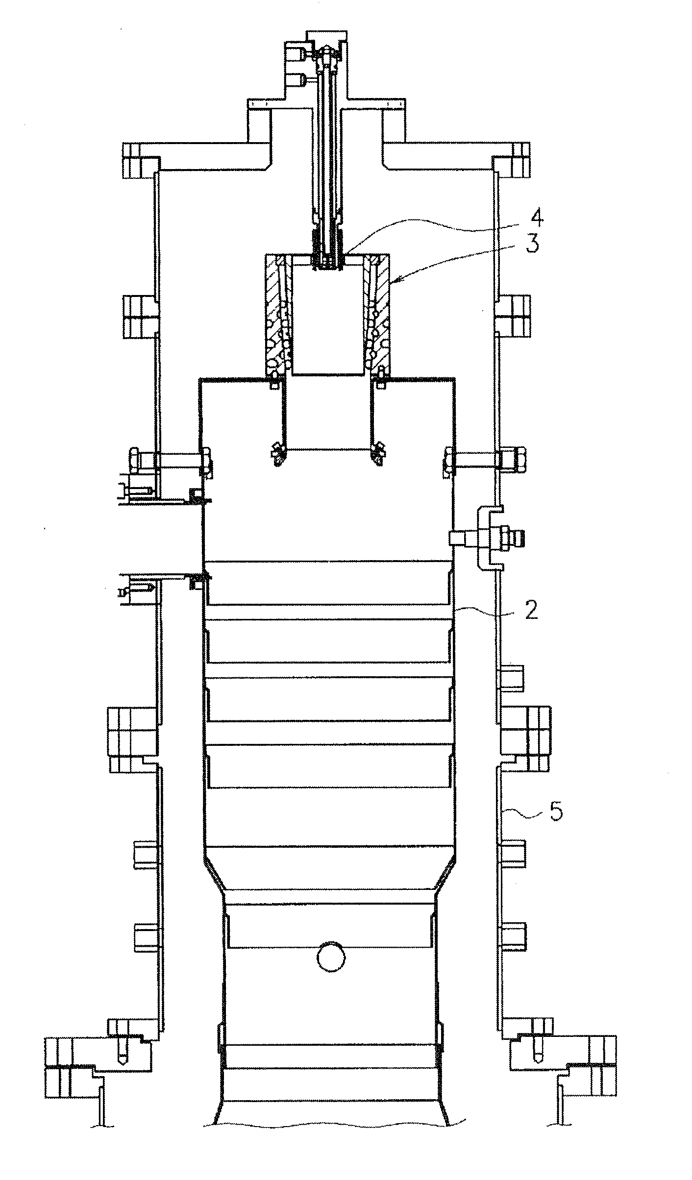
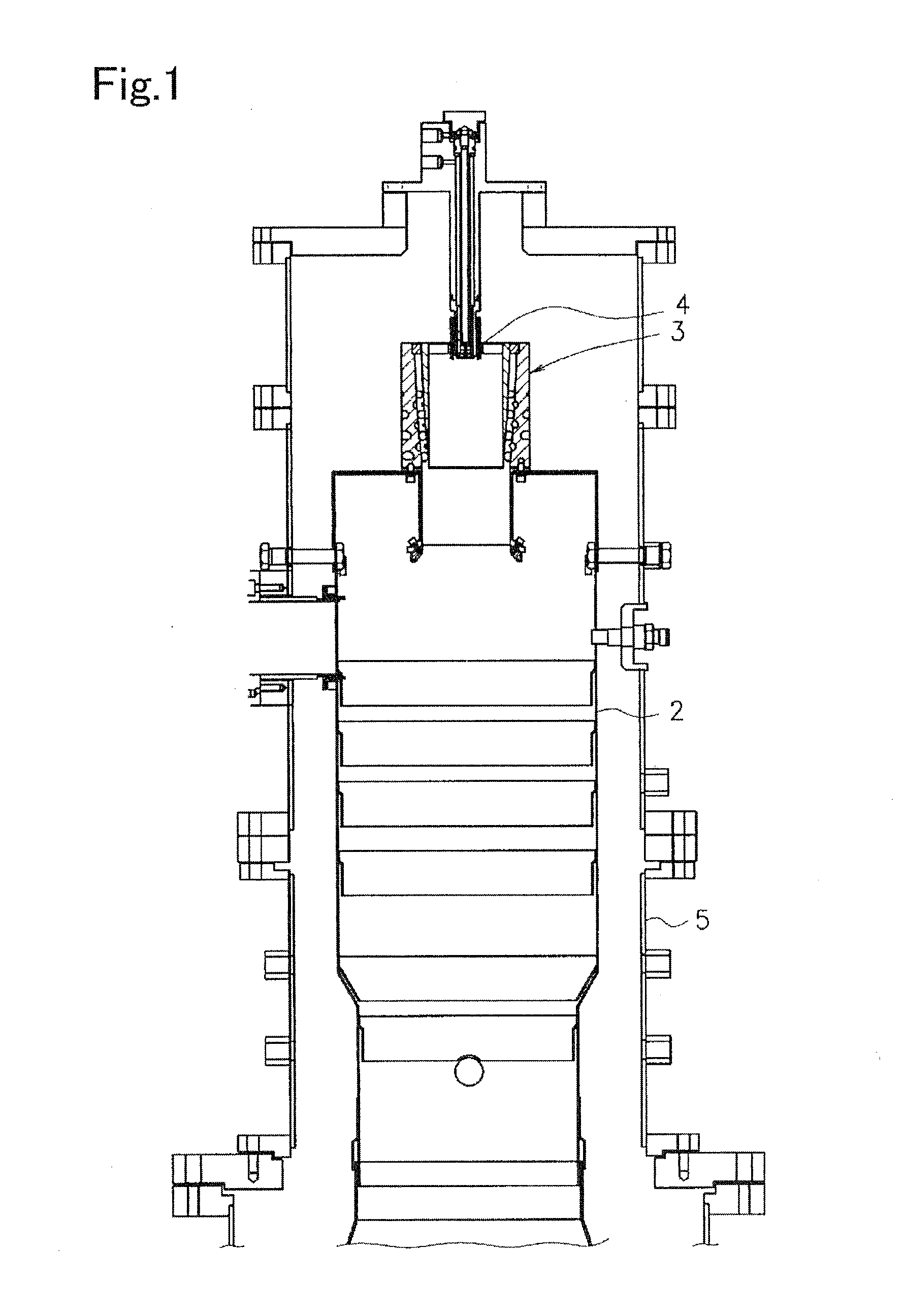
[0030]Referring to FIG. 1, a general structure of a gas turbine combustor 1 will be described.
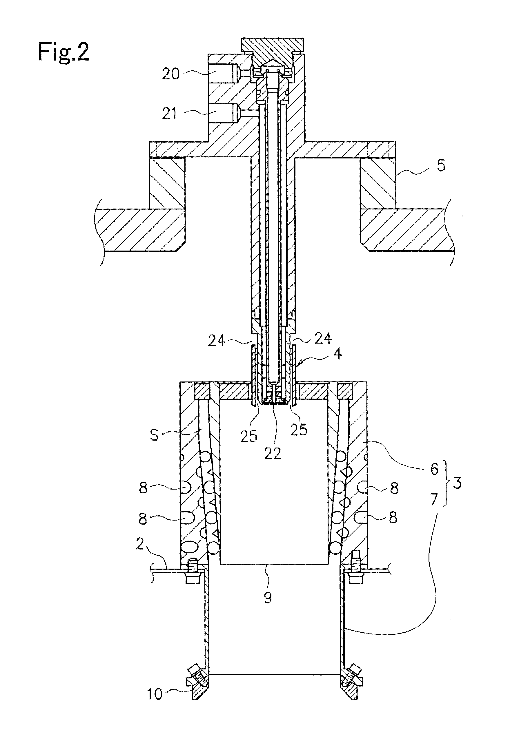
[0031]The gas turbine combustor 1 includes a substantially cylindrical combustion cylinder 2. The combustion cylinder 2 has a top portion closed, and a lower opening communicated with an exhaust side of a not shown gas turbine. The top portion of the combustion cylinder 2 is provided with a premixing tube 3, which will be described in detail later. A top portion of the premixing tube 3 is provided with a pressure injection unit 4 as a fuel supply unit. The combustion cylinder 2 and the premixing tube 3 are encased with an outer cylinder 5 communicated with a compressed air inlet of a not shown turbo-compressor. A part of a fuel supply system connected to the pressure injection unit 4 is guided to the outside while penetrating the top portion of the outer cylinder 5.
[0032]Referring to FIGS. 1 and 2, at the center position of the top portion of the combustion cylinder 2, the premixing tube 3...
second embodiment
[0057]An example of a structure of an inner diameter enlarging portion 30 for a gas turbine combustor will be described referring to FIGS. 8A to 8C.
[0058]FIGS. 8A to 8C show a circumferential surface portion 31 with a fan-shape cross section, having a predetermined radius at the center angle of 90° as a curved portion on an inner circumferential edge of the inner diameter enlarging portion 30. FIG. 8A represents the circumferential surface portion with a radius of 30 mm, FIG. 8B represents the circumferential surface portion with a radius of 20 mm, and FIG. 8C represents the circumferential surface portion with a radius of 10 mm, respectively. Each of the respective portions is attached to the open end of the protruding wall 7 of the premixing tube 3 so as to be continued with the inner circumferential surface of the protruding wall 7, and to serve as the inner diameter enlarging portion 30 to expand the inner diameter toward the combustion cylinder 2 in the downward direction. It ...
PUM
 Abstract
Description
Claims
Application Information
 - R&D
- Intellectual Property
- Life Sciences
- Materials
- Tech Scout
- Unparalleled Data Quality
- Higher Quality Content
- 60% Fewer Hallucinations
Browse by: Latest US Patents, China's latest patents, Technical Efficacy Thesaurus, Application Domain, Technology Topic, Popular Technical Reports.
© 2025 PatSnap. All rights reserved.Legal|Privacy policy|Modern Slavery Act Transparency Statement|Sitemap|About US| Contact US: help@patsnap.com


