
LCD backlight component coatings for reducing light losses and improving in-stack light collimation

a backlight and component technology, applied in the field of lcd backlights, can solve the problems of not contributing to the light usable by the lcd panel, not being able to optimally capture values, and not being able to achieve the effect of reducing light loss, reducing cost, and improving backlight efficiency

Inactive Publication Date: 2014-05-15
LIGHT POLYMERS HLDG
View PDF0 Cites 30 Cited by
  • Summary
  • Abstract
  • Description
  • Claims
  • Application Information

AI Technical Summary

Benefits of technology

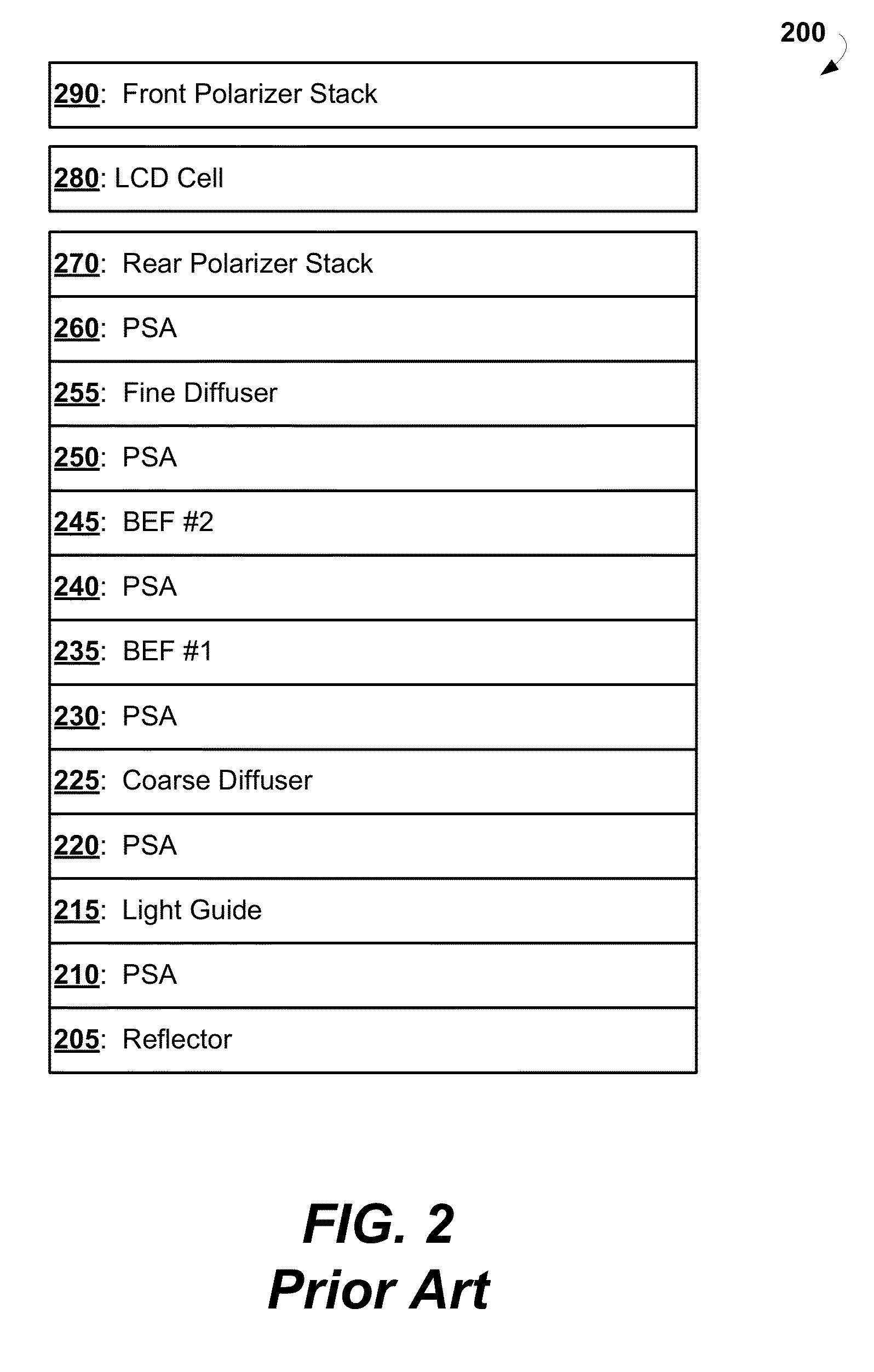
The present patent provides single layer or multilayered coatings for the reflector, light guide, diffusers, and BEFs in an LCD backlight. This results in a more efficient backlight that reduces light losses and improves light collimation. The high index of refraction coatings and pressure sensitive adhesives are intelligently selected to collimate light propagating through the backlight, reduce light scattering, and reduce light losses. The method for forming a multilayer stack for reducing light losses involves depositing a high index of refraction coating onto the elements of the stack and then depositing a pressure sensitive adhesive onto the high index of refraction coating. This results in a more efficient backlight assembly with reduced light losses and improved light collimation.

Problems solved by technology

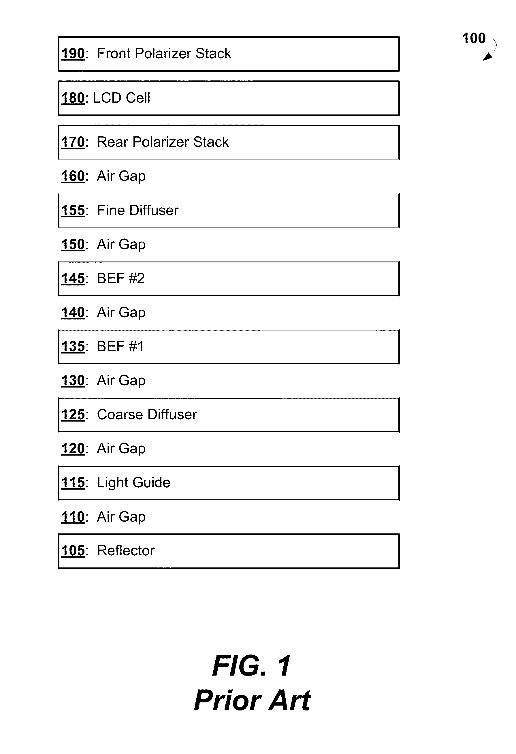
These values may not be sufficient to optimally capture the light in an LCD backlight and direct it toward the LCD panel with optimized collimation of light when air gaps separate the elements in the backlight.
Some of the light in this solid angle and the skew rays may lie outside the solid angle of efficient capture of the subsequent BEF in the backlight unit and as a result does not contribute to the light usable by the LCD panel.
Some of the light in this solid angle and the skew rays may lie outside the solid angle of efficient capture of the subsequent BEF or fine diffuser and as a result does not contribute to the light usable by the LCD panel.
This may reduce the efficiency of the backlight.
Some of this light in this solid angle and the skew rays cannot be efficiently processed by the front and rear polarizer stacks or the LCD panel and as a result does not contribute to the light usable by the LCD panel.
Current technology reflectors, light guides, diffusers and BEFs do not meet this criterion since these components redirect light to lie within a specified solid angle with respect to the normal to the backlight assembly and all scatter light producing skew rays that fall outside the specified solid angle of these components.
At each air gap, additional light can be lost due to reflections with scattering caused by index of refraction mismatches between the optical components and the air gaps, further reducing the light processing efficiency of the overall backlight unit.
Additionally, a PSA with a refractive index that matches the indexes of the reflector and light guide can negate the functionality of these components.
There are low index of refraction coatings that can reduce reflections at the reflector, light guide, diffusers and BEFs air gap boundaries These coatings are however complex and prohibitively expensive for use in a consumer LCD backlight.
These components may have problems similar to those described with reference to the edge lighted backlight unit.
The reflections, scattering, and refractions of light of various kinds or nature may generate problems such as unwanted changes in color, brightness, and contrast in addition to said light losses.

Method used


Image

  • LCD backlight component coatings for reducing light losses and improving in-stack light collimation
  • LCD backlight component coatings for reducing light losses and improving in-stack light collimation
  • LCD backlight component coatings for reducing light losses and improving in-stack light collimation

Examples


example 1

[0102]This example describes synthesis of poly(2,2′-disulfo-4,4′-benzidine isophthalamide) cesium salt (i.e., structure (XII)):

[0103]In particular, 1.377 g (0.004 mol) of 4,4′-diaminobiphenyl-2,2′-disulfonic acid was mixed with 1.2 g (0.008 mol) of Cesium hydroxide monohydrate and 40 ml of water and stirred with dispersing stirrer till dissolving, then 0.672 g (0.008 mol) of sodium bicarbonate was added to the solution and stirred. While stirring the obtained solution at high speed (2500 rpm), a solution of 0.812 g (0.004 mol) of isophthaloyl dichloride (IPC) in dried toluene (15 mL) was gradually added within 5 minutes. The stirring was continued for 5 more minutes, and viscous white emulsion was formed. Then the emulsion was diluted with 40 ml of water, and the stirring speed was reduced to 100 rpm. After the reaction mass has been homogenized, the polymer was precipitated by adding 250 ml of acetone. Fibrous sediment was filtered and dried.

[0104]Weight average molar mass of the p...

example 2

[0105]Example 2 describes synthesis of 2,2′-disulfo-4,4′-benzidine terephthalamide-isophthalamide copolymer cesium salt (copolymer of structures (XI) and (XII):

[0106]The same method of synthesis as in the Example 1 can be used for preparation of the copolymers of different molar ratio. In particular, 4.098 g (0.012 mol) of 4,4′-diaminobiphenyl-2,2′-disulfonic acid was mixed with 4.02 g (0.024 mol) of cesium hydroxide monohydrate in water (150 ml) in a 1 L beaker and stirred until the solid was completely dissolved. Then 3.91 g (0.012 mol) of sodium carbonate was added to the solution and stirred at room temperature until dissolved. Then toluene (25 ml) was added. Upon stirring the obtained solution at 7000 rpm, a solution of 2.41 g (0.012 mol) of terephthaloyl chloride (TPC) and 2.41 g (0.012 mol) of isophthaloyl chloride (IPC) in toluene (25 ml) were added. The resulting mixture thickened in about 3 minutes. The stirrer was stopped, 150 ml of ethanol was added, and the thickened mi...

example 3

[0107]Example 3 describes synthesis of poly(2,2′disulpho-4,4′ benzidine 1,4,5,8-naphtalen tetracarboxylic acid diimid) triethylammonium salt (i.e., the structure (XVI)):

[0108]4.023 g (0.015 mol) of 1,4,5,8-naphtaline tetracarbonic acid dianhydride and 5.165 g (0.015 mol) of 2,2′-disulfobenzidine and 0.6 g of benzoic acid (catalyst) were charged into a three-neck flask equipped with an agitator and a capillary tube for argon purging. With argon flow turned on, 40 ml of molten phenol was added to the flask. Then the flask was placed in a water bath at 80° C., and the content was agitated until homogeneous mixture was obtained. 4.6 ml of triethylamine was added to the mixture, and agitation was kept on for 1 hour to yield solution. Then the temperature was raised successively to 100, 120, and 150° C. At 100 and 120° C., agitation was held for 1 hour at each temperature. During this procedure, the solution keeps on getting thicker. Time of agitation at 150° C. is 4 to 6 hours.

[0109]The ...


PUM

PropertyMeasurementUnit
refractive indexaaaaaaaaaa

Abstract

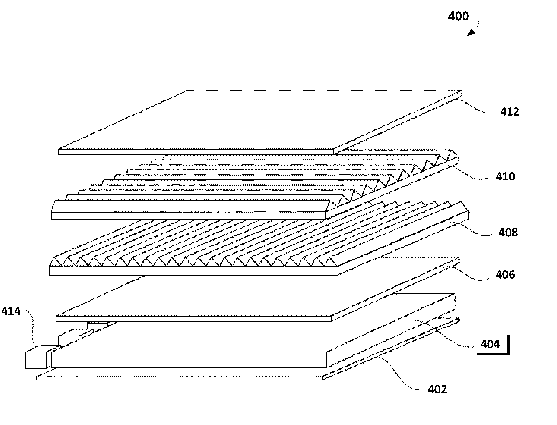
Provided are multilayer stacks for backlight units in LCD panels and methods for forming thereof. The stacks include refractive index matching layers and pressure sensitive adhesives to minimize light losses. More particularly, the stacks comprise a reflector, a light guide, a course diffuser, one or more brightness enhancing films, and a fine diffuser. A refractive index matching layer is deposited onto at least one surface of the backlight components. A pressure sensitive adhesive is deposited onto the refractive index matching layers. Alternatively, the stacks comprise two or more refractive index matching layers on each surface of the backlight components and retain an air gap between the backlight components. The refractive index matching interlayers are based on a polymer solution having about 0.1%-30% by weight of specific rigid rod-like polymer molecules. The molecules may include various cores, spacers, and sides groups to ensure their solubility, viscosity, and cross-linking ability.

Description

CROSS-REFERENCE TO RELATED APPLICATIONS[0001]This application is a continuation-in-part of U.S. patent application Ser. No. 13 / 869,041, entitled “DEPOSITING POLYMER SOLUTIONS TO FORM OPTICAL ELEMENTS,” filed on Apr. 24, 2013, which is incorporated herein by reference in its entirety.TECHNICAL FIELD[0002]This disclosure relates generally to liquid crystal display (LCD) backlights and, more particularly, to reducing light losses due to reflections at the surfaces of optical elements, to reducing light scattering at the surfaces of optical elements, and to improving light collimation at the surfaces of optical elements in LCD backlights.DESCRIPTION OF RELATED ART[0003]The approaches described in this section could be pursued, but are not necessarily approaches that have previously been conceived or pursued. Therefore, unless otherwise indicated, it should not be assumed that any of the approaches described in this section qualify as prior art merely by virtue of their inclusion in this...

Claims


Application Information

Patent Timeline
Patent Type & Authority Applications(United States)
IPC IPC(8): F21V8/00
CPCG02B6/0065G02B6/005Y10T29/49885
Inventor MILLER, SAMUELMCCONNAUGHEY, MARCMOROZOV, EVGENYPOLIAKOV, EVGENI
Owner LIGHT POLYMERS HLDG
Learn More