Pin driven flexible chamber abrading workholder

a flexible chamber and workholder technology, applied in the direction of lapping machines, manufacturing tools, grinding machines, etc., can solve the problems of large cost savings and high workpiece production rates, and achieve the effect of high vacuum

Inactive Publication Date: 2014-05-08
DUESCHER WAYNE O
View PDF40 Cites 17 Cited by
  • Summary
  • Abstract
  • Description
  • Claims
  • Application Information

AI Technical Summary

Benefits of technology

[0025]Conventional flexible elastomeric pneumatic-chamber wafer carrier heads have a substantial disadvantage in that the vertical walls of the elastomeric chambers are very weak in a lateral or horizontal direction. The abrading pressures and vacuum that are applied to these sealed chambers are typically very small, in part, to avoid very substantial lateral deflections of the elastomer wa

Problems solved by technology

High abrading speeds result in high workpie

Method used


Image

  • Pin driven flexible chamber abrading workholder
  • Pin driven flexible chamber abrading workholder
  • Pin driven flexible chamber abrading workholder

Examples


Embodiment Construction

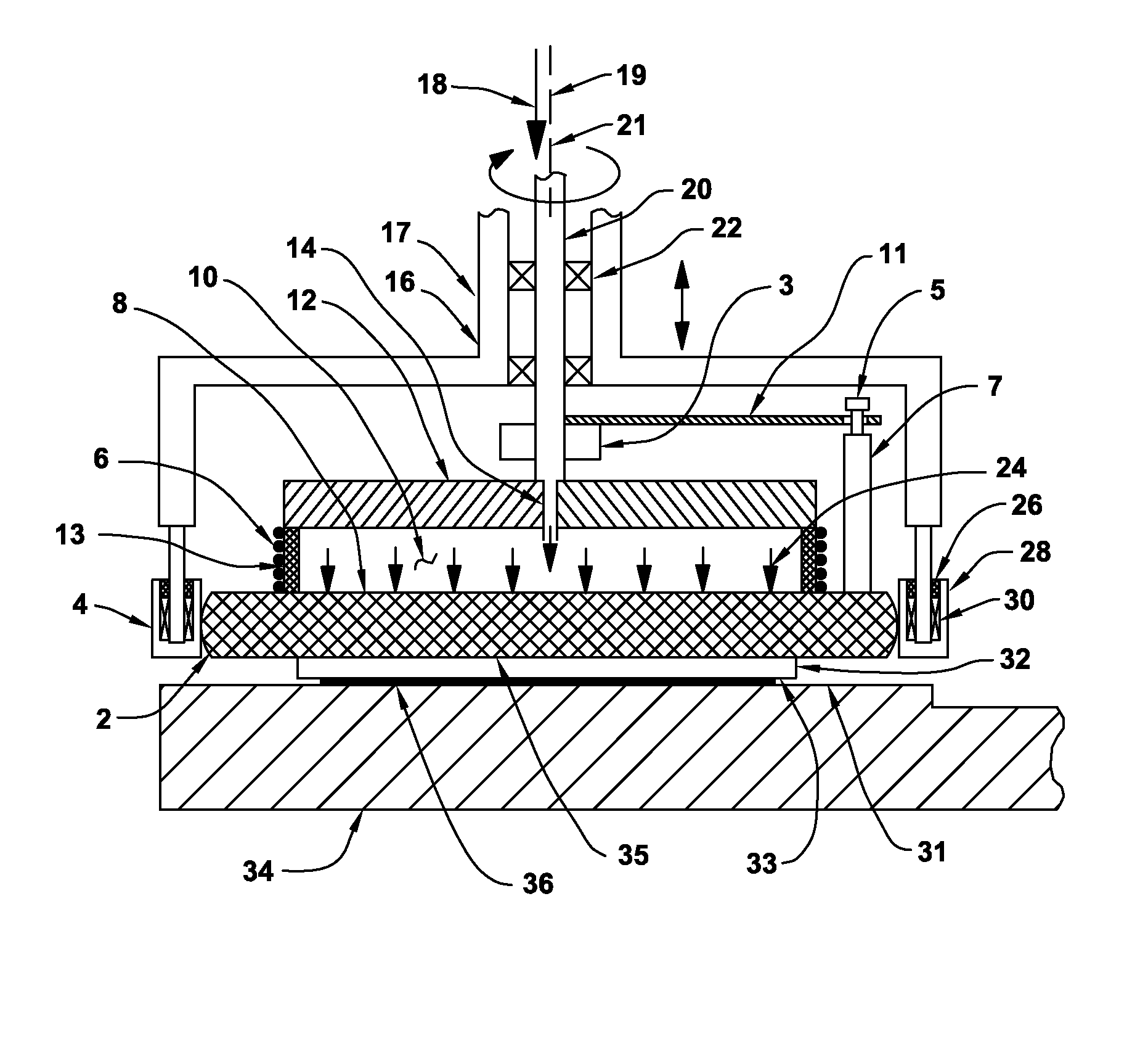
[0084]FIG. 1 is a cross section view of a sliding-contact drive-pin rotationally driven floating workpiece carrier used for lapping or polishing semiconductor wafers or other workpiece substrates. A stationary workpiece carrier head 17 has a flat-surfaced workpiece 32 that is attached to a floating workpiece carrier rotor 35 that is rotationally driven by a drive-pin device 5. A nominally-horizontal drive plate 12 is attached to a hollow drive shaft 20 having a rotation axis 19 that is supported by bearings 22 that are supported by a stationary carrier housing 16 where the carrier housing 16 can be raised and lowered in a vertical direction.

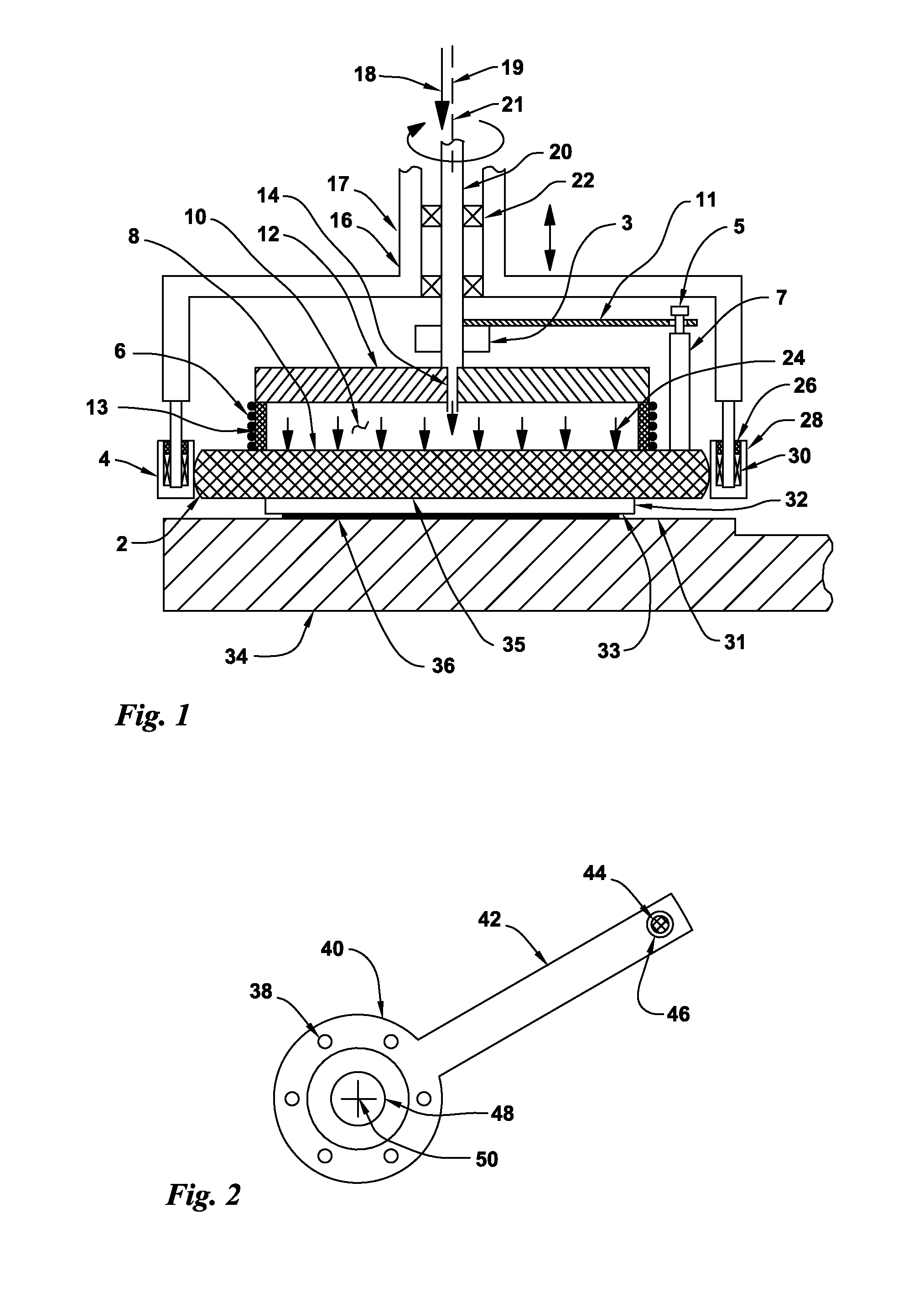
[0085]A nominally-rigid rotational drive arm 11 is attached to the hollow drive shaft 20 where rotation of the hollow drive shaft 20 rotates the rotational drive arm 11. The drive-pin device 5 is attached a rigid annular member 7 or multiple individual posts 7 that is / are attached to the workpiece carrier rotor 35 which allows the drive-pin devic...


PUM

PropertyMeasurementUnit
Thicknessaaaaaaaaaa
Pressureaaaaaaaaaa
Diameteraaaaaaaaaa

Abstract

Flat-surfaced workpieces such as semiconductor wafers or sapphire disks are attached to a rotatable floating workpiece holder carrier that is supported by a pressurized-air flexible elastomer sealed air-chamber device and is rotationally driven by a lug-pin device. The rotating wafer carrier rotor is restrained by a set of idlers that are attached to a stationary housing to provide rigid support against abrading forces. The abrading system can be operated at the very high abrading speeds used in high speed flat lapping with raised-island abrasive disks. The range of abrading pressures is large and the device can provide a wide range of torque to rotate the workholder. Vacuum can also be applied to the elastomer chamber to quickly move the wafer away from the abrading surface. Internal constraints limit the axial, lateral and circumferential motion of the workholder. Wafers can be quickly attached to the workpiece carrier with vacuum.

Description

CROSS REFERENCE TO RELATED APPLICATIONS[0001]This invention is a continuation-in-part of U.S. patent application Ser. No. 14 / 148,729 filed Jan. 7, 2014 that is a continuation-in-part of U.S. patent application Ser. No. 13 / 869,198 filed Apr. 24, 2013 that is a continuation-in-part of U.S. patent application Ser. No. 13 / 662,863 filed Oct. 29, 2012. These are each incorporated herein by reference in their entirety.BACKGROUND OF THE INVENTIONField of the Invention[0002]The present invention relates to the field of abrasive treatment of surfaces such as grinding, polishing and lapping. In particular, the present invention relates to a high speed semiconductor wafer or abrasive lapping workholder system for use with single-sided abrading machines that have rotary abrasive coated flat-surfaced platens. The slide-pin drive workholders employed here allow the workpiece substrates to be rotated at the same desired high rotation speeds as the platens. Often these platen and workholder speeds e...

Claims


Application Information

Patent Timeline
IPC IPC(8): B24B37/30B24B37/04
CPCB24B37/042B24B37/30B24B37/10
Inventor DUESCHER, WAYNE O.
Owner DUESCHER WAYNE O
Why Eureka
Try Eureka