High-frequency power supply for plasma and icp optical emission spectrometer using the same

a technology of optical emission spectrometer and high-frequency power supply, which is applied in the direction of optical radiation measurement, instruments, spectrometry/spectrophotometry/monochromators, etc., can solve the problems of insufficient cooling of compact ceramic capacitors, ls (inductors) and pulse transformers, insufficient cooling, etc., to prevent short circuit or corrosion, prevent the effect of being broken

Active Publication Date: 2014-05-01
SHIMADZU CORP
View PDF13 Cites 6 Cited by
  • Summary
  • Abstract
  • Description
  • Claims
  • Application Information

AI Technical Summary

Benefits of technology

The present invention relates to a high-frequency power supply for plasma which is designed to prevent dust and other contaminants from entering the housing of the power supply. This is achieved by creating a sealed space within the housing and using a cooling block to release heat and cool the elements mounted on the high-frequency circuit substrate. This prevents damage to the elements and ensures continued operation of the plasma flame.

Problems solved by technology

A number of transistors and large-scale capacitors are mounted on the upper surface of the high-frequency circuit substrate 132 in plate form in the above-described ICP optical emission spectrometer 200, which also has amplifying circuits in multiple stages, and therefore is costly and large.
However, the cooling of the compact ceramic capacitors, Ls (inductors) and pulse transformers was insufficient.
Furthermore, the cooling was insufficient even when only the cooling fan for allowing air to flow was used to cool the power MOSFETs, compact ceramic capacitors, pulse transformers, wires, Ls (inductors) and bypass capacitors as a forced air cooling system.

Method used


Image

  • High-frequency power supply for plasma and icp optical emission spectrometer using the same
  • High-frequency power supply for plasma and icp optical emission spectrometer using the same
  • High-frequency power supply for plasma and icp optical emission spectrometer using the same

Examples


examples

[0052]In the following, the present invention is described in further detail by reference to examples, but the present invention is not limited to these examples.

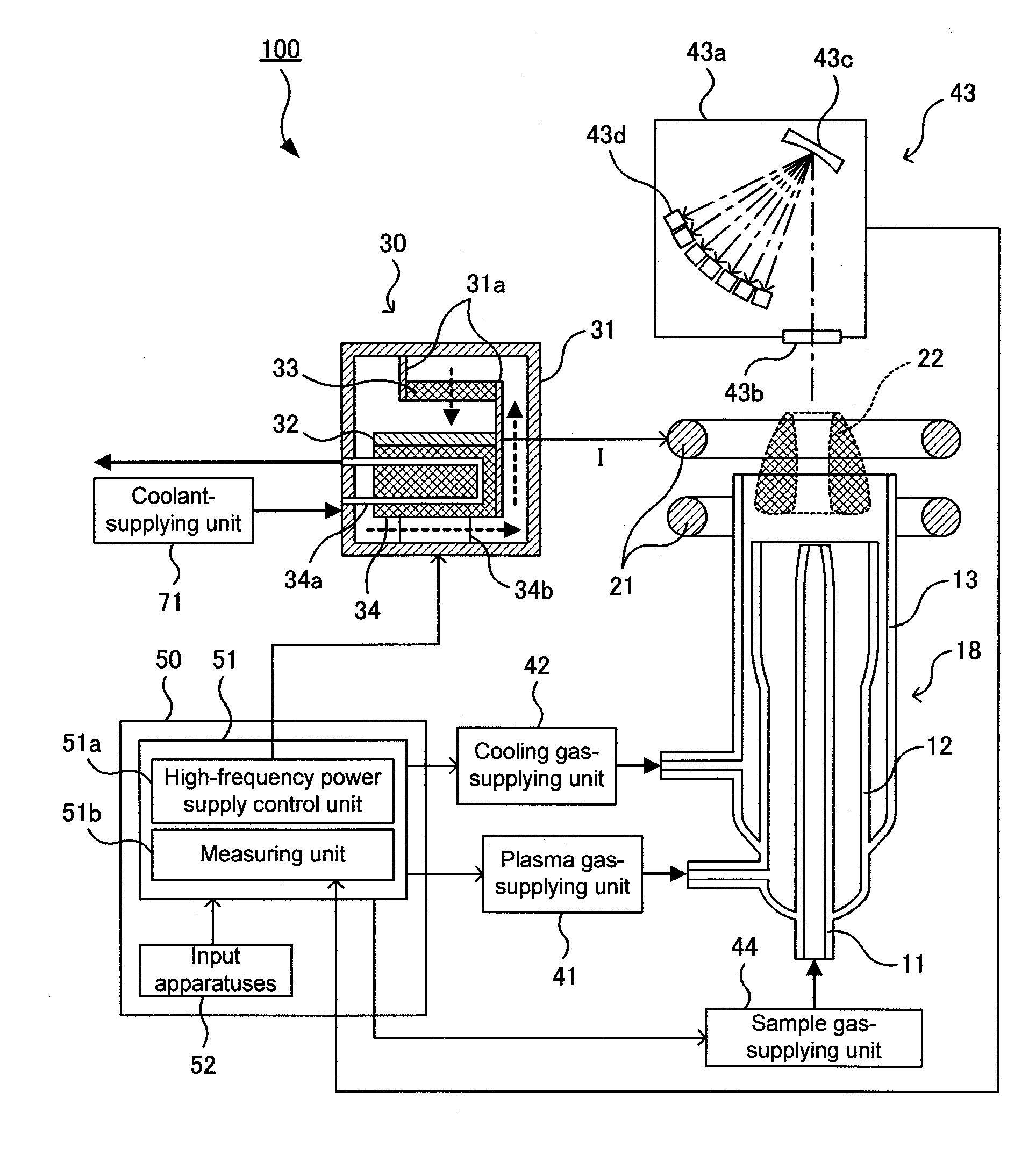
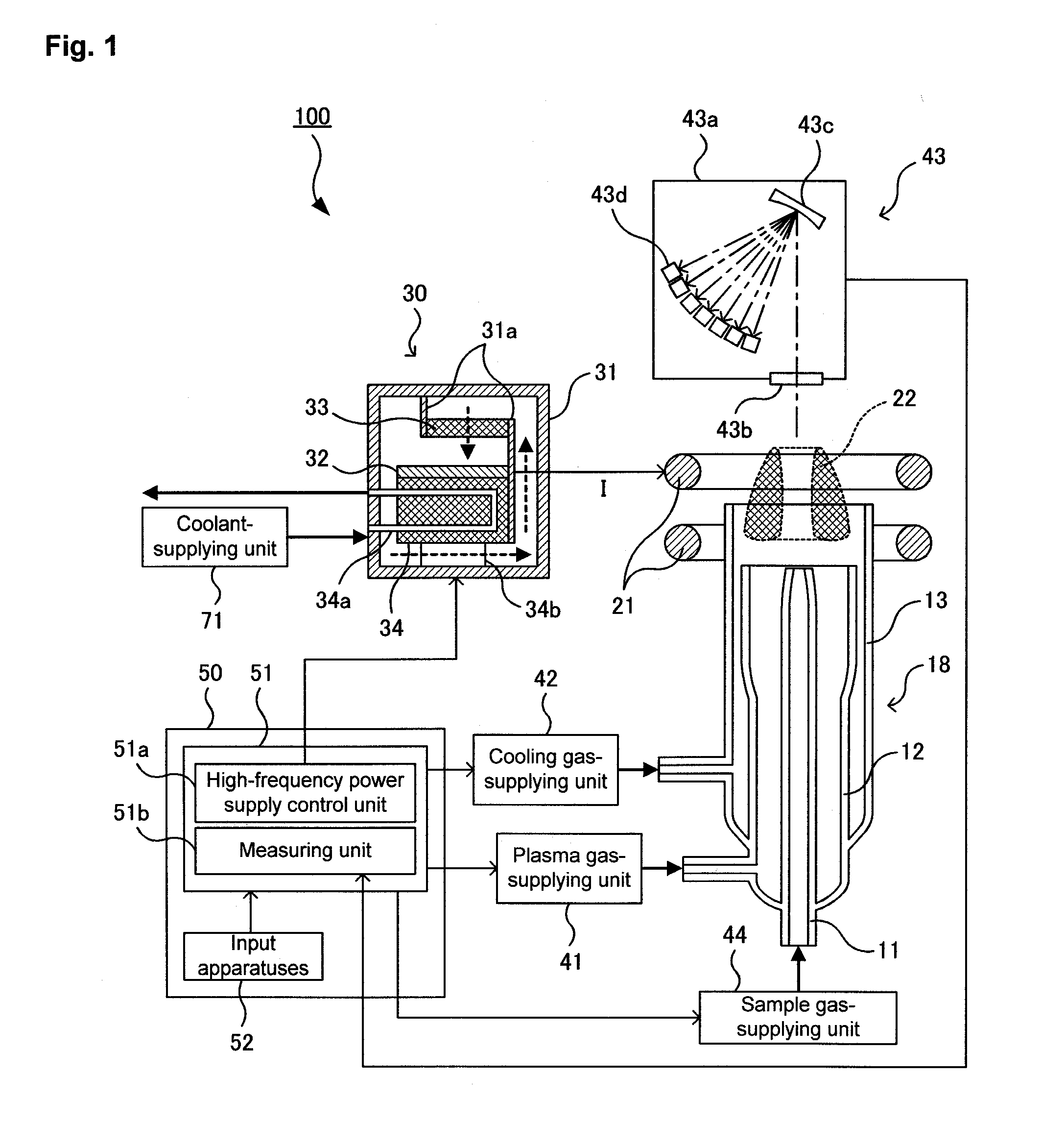
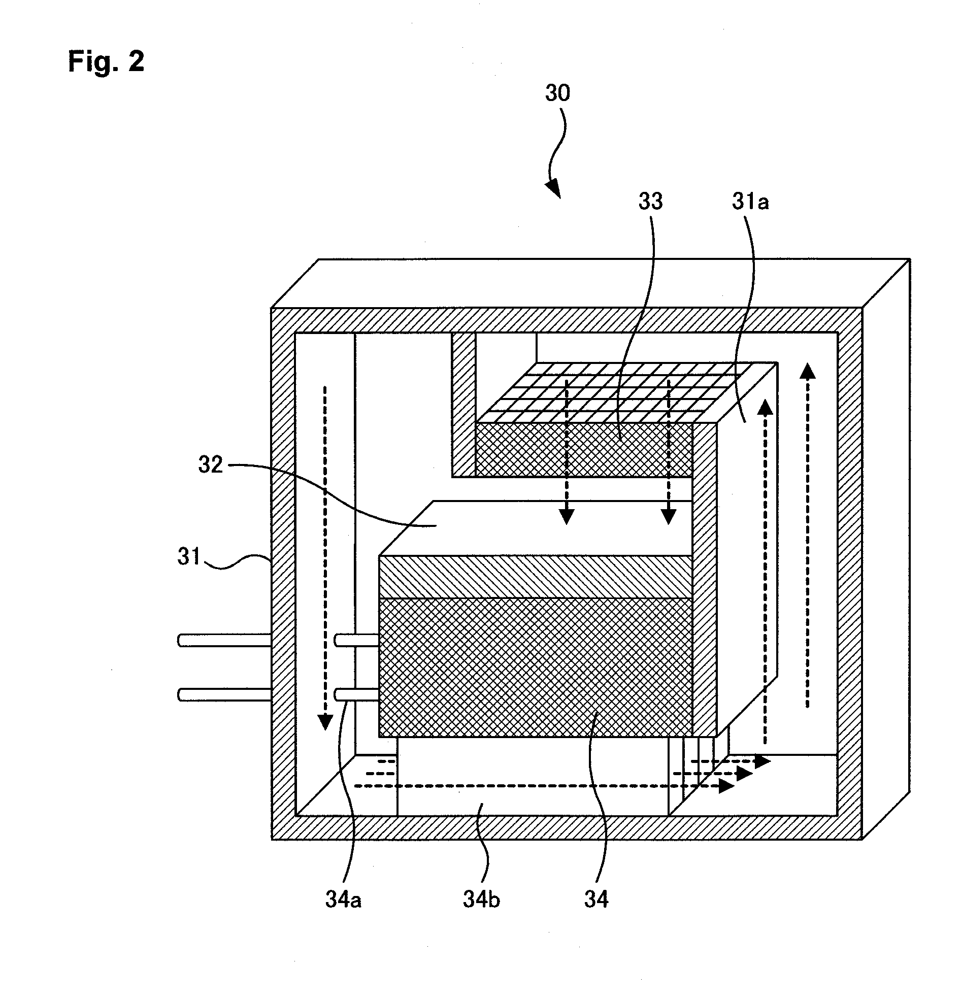
[0053]A heat network of a high-frequency power supply 30 for plasma was fabricated according to an example, and the surface temperature of the elements mounted on the high-frequency circuit substrate 32 were calculated using the following formulas when the flowing current was 20.7 Arms.

[0054]FIG. 4 is a diagram showing a heat network. Here, Tw is the temperature of the cooling water, Tb is the surface temperature of the cooling copper block 34, and Tg is the air temperature. In addition, T1 is the surface temperature of the pulse transformer 32a, T2 is the surface temperature of the wire 32b, T3 is the surface temperature of the compact ceramic capacitor 32c, T9 is the surface temperature of the bypass capacitor 32f, T5 is the surface temperature of the power MOSFET 32e, and T4 is the surface temperature of the L (inductor)...


PUM


Abstract

In a high-frequency power supply for plasma having a housing and a high-frequency circuit substrate placed inside the housing elements for supplying a high-frequency current to a high-frequency inductive coil are mounted on the high-frequency circuit substrate, a cooling block for cooling the high-frequency circuit substrate, a fan for sending air to the elements on the high-frequency circuit substrate as wind are further provided, and fins for allowing air to flow through so that the air is cooled are formed on the surface of the cooling block. The housing is provided with an air path for supplying the air that has flown through the fins to the absorbing side of the fan.

Description

TECHNICAL FIELD[0001]The present invention relates to a high-frequency power supply for plasma and an ICP optical emission spectrometer using the same.BACKGROUND ART[0002]In an ICP optical emission spectrometer, a sample is introduced into a plasma flame so as to emit light through excitation. The thus-emitted light is dispersed through a grating so as to be detected by a photodetector, and as a result, an emission spectrum is acquired. In addition, an element contained in the sample is qualitatively analyzed by the type of wavelength in the spectrum line (bright line spectrum) that appears in the emission spectrum, and furthermore, the element is quantitatively analyzed by the intensity of this bright line spectrum (see Patent Document 1).[0003]FIG. 5 is a schematic diagram showing the structure of an example of a conventional ICP optical emission spectrometer. An ICP optical emission spectrometer 200 is provided with a plasma torch 18 for optical emission spectrometry from which a...

Claims


Application Information

Patent Timeline
IPC IPC(8): H05H1/24G01N21/73
CPCH05H1/24G01N21/73H05H1/30
Inventor MATSUSHITA, TOMOYOSHI
Owner SHIMADZU CORP
Why Eureka
Try Eureka